How to Make a Sprite Sheet from a 3D Model Using Blender and ImageMagick
If you want to make 2D sprites with complex animations, 3D is actually a great place to start.
Summary
- We will understand why using 3D models to make 2D sprites can be an efficient method for making sprites with a lot of animations.
- We will make a basic 3D model with a toon shader and a basic animation. If you are familiar with these steps, you may skip this section.
- We will take your existing 3D animation and render out all the images for the animation.
- Finally, we will use an ImageMagick command to roll-up the images into one sprite sheet.
Introduction
When working on my platformer, Flick!, I had a choice to make. Since my game is 2D, I could draw my player sprite and its animations in a more traditional way, using a sprite editor or an animation program like Adobe Animate. However, doing this would be incredibly slow, especially with my limited art skills.
Taking a look around the internet, I’ve seen some people use Blender to make sprites. The approach was relatively simple - you would make a 3D model, then you would render the 3D model to a static image. This had me thinking - if I could render an animation from a 3D model, I could use an external tool like ImageMagick to compile the images into a sprite sheet. Plus, I’ve already had experience with toon shaders, so I could still get a 2D looking sprite by using 3D instead!
The major advantage of using this approach, rather than drawing sprites using 2D software, is that it is easier and more scalable to make 3D animations. Yes, there is overhead in setting up the 3D model and rig, but if you have the need for a ton of animations (such as for a playable character), this method scales very well. In addition, you may also consider this method if you want to reuse animations across characters. With a similar rig, you can easily transfer animations in the future to other characters, which is impossible to do with traditional 2D animation. Lastly, you may consider this approach if you’re more technically inclined, like me, and would prefer to let the 3D shader do the job of enabling your art style.
Before We Begin
This article assumes you already have a 3D animation. If you are new to the 3D process in Blender, I have left some of my favorite tutorial links here you can reference (thanks to Royal Skies, he makes great content!):
- https://www.youtube.com/playlist?list=PLZpDYt0cyiutkKkIZgrja6Hdr9e5prBsu
- https://www.youtube.com/playlist?list=PLZpDYt0cyiuvuzHga3apBwSaCD7MTrv8L
- https://www.youtube.com/playlist?list=PLZpDYt0cyiut1oZv6zyWgDnyBJu4U1jwJ
ImageMagick
I decided to use ImageMagick because I was unable to find any native Blender solution to make sprite sheets. I also remember using ImageMagick in the past for something, so I already had some comfort with using it. Plus, ImageMagick is free and open source and has been around for a long time, so it’s a nice tool to have alongside Blender for this approach.
Most Linux distros come with ImageMagick installed by default. However, if you are using Windows or MacOS, you’ll have to install it manually. You can find the installation instructions here:
https://imagemagick.org/script/download.php
Making a Basic 3D Model and Animation
In this section, I’ll go over how I went about modeling my assets for Flick! Since colored beans are the collectable used in the game, we will model a bean. For future sections, I’ll use a basic enemy I made for the game, but this bean will also suffice for following along. Originally, I made a separate YouTube video on this particular section, but I wanted to consolidate it here in this article. If you’re interested in watching the video instead, you can find it here:
Initial Setup
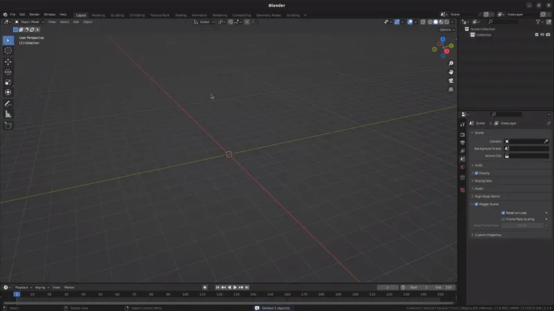
Once you open Blender, feel free to delete all three of the initial objects, so we can start from scratch. To do this quickly, press the A key, followed by the DEL key to quickly delete all of them.
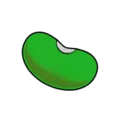
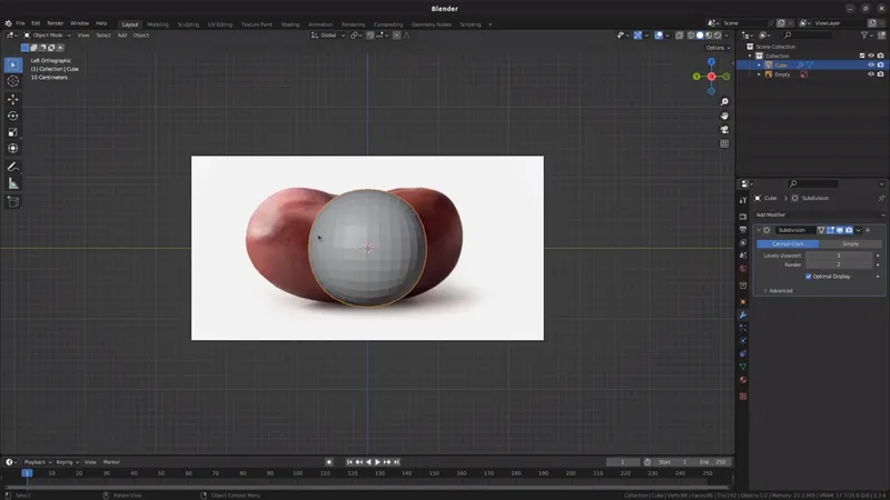
Next, we will import a reference image. If you don’t have one, it’s not necessary for making a simple object like a bean. However, references tend to help with more complex models. Feel free to also use the image below as a reference image for your scene, if you choose to follow along exactly with this tutorial. Just right-click it in your browser, and save it to your computer. You can also just download a reference image off of Google Images. You’re only using it as a reference, so don’t be worried about copying!
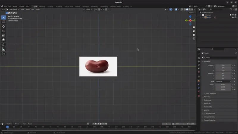
To import the reference image into Blender, I recommend first pressing CTRL+Numpad3. This will set the view mode to Left Orthographic, which will make it easier to place vertices around the reference later. You can now drag the image file directly into Blender, and Blender will import it for you. To center the image in the viewport, press ALT+G to reset the position of the image.
Modeling the Bean
With the reference image in place, it’s now time to start modeling the bean.
When modeling in the traditional way, primitives such as cubes, spheres and cylinders are essential building blocks. By starting with one primitive, and then shaping the vertices on it, you can eventually reach your desired shape. We will be using a cube to start, as it’s the easiest to work with. Press SHIFT+A to bring up the Add menu, and select the Cube to add one to your scene.
Now, you may be wondering why a cube was used instead of a sphere, given the bean is round. The answer is simple - we can use a Subdivision Surface modifier to round out the edges. That way, it’s still easier to move the vertices of the cube while getting the rounded effect. To add the Subdivision Surface modifier, select the cube, and then navigate to the Modifiers tab. Select Subdivision Surface from the options. In my example, I have the subdivision level set to 3, but you can tweak this value as desired. Since the model will be used to generate a 2D image, the number of polygons doesn’t matter nearly as much for performance, so feel free to bump up the fidelity of subdivisions up to what your computer can handle.
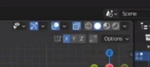
Next, it’s time to manipulate the cube to become bean shaped. This can be done in Edit mode. Press TAB to go into Edit mode. In the top right corner of the Blender view, turn on X-Ray and X Mirror. The X-Ray feature is valuable for selecting vertices, edges or faces that are out of view for the model. Given it’s a cube, there will be two vertices in each corner, rather than one, so this helps you be able to select both the front and back vertices. X Mirror will make identical changes to the opposite side of the model we edit, saving valuable time. Remember, the view is Left Orthographic, not Front Orthographic, so X Mirror actually mirrors your front and back in this case.
With the helper functions set up, the next thing to do would be to add some more geometry to work with. You could manipulate the four corners of the cube all you like, but there’s only so much you can do to shape it. By adding more geometry, it’ll give you more vertices to work with, making it possible to capture the bean shape. One of the most common tools is the Loop Cut and Slide tool, which will bisect the mesh where specified. Press CTRL+R to initialize the Loop Cut tool. Use the mouse wheel to increase the number of cuts, as we will utilize more than one cut anyway. Left click to confirm.
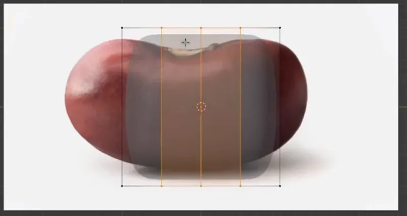
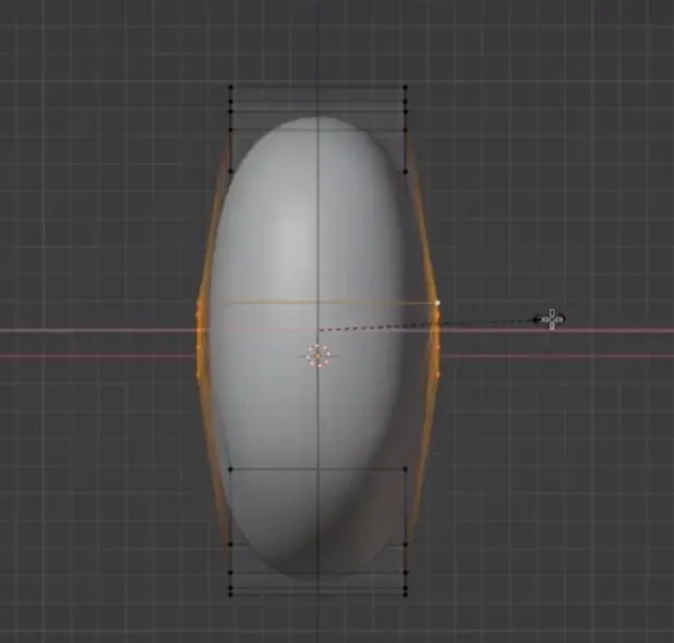
It’s now time to move the points to follow the reference. Using the box selection tool, draw a box around the one of the corners to select both the front and back vertices. The box selection tool should be enabled by default, but you can check this button here to enable it if not. Since we have X-Ray on, the vertex in the back also gets selected. Then, use the G key to move the vertices roughly to the positions matching the reference, as shown in the screenshot below. Repeat for all the points. You may also need to add more loop cuts to get the desired shape, so feel free to do that too.
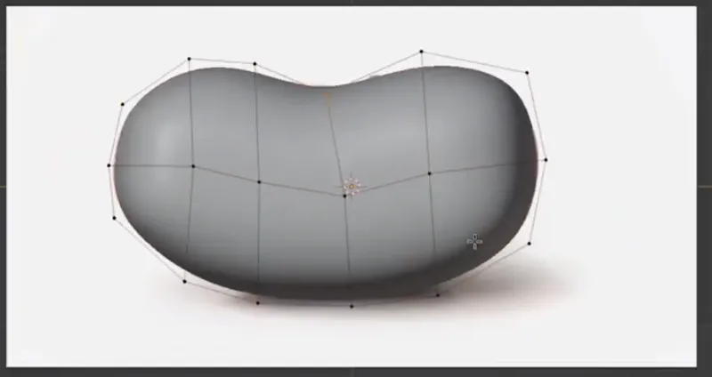
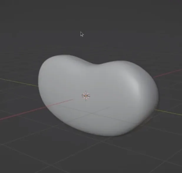
To make the front of the bean, switch to Front Orthographic view using the Numpad1 key and making a shape roughly like mine below. For more complex models, such as characters, you would typically use a reference image for both the front and the left or right side. Since this is a simple bean, doing a rough approximation is fine.
For final touches, switching between Perspective view, Front Orthographic view and Left Orthographic view to look at the whole model is helpful. Middle-click on the mouse to go into Perspective view. Simply tweak the points until it feels right to you.
Making the Toon Shader
To get the cartoony look, we will build what’s called a toon shader. A shader is a program that influences the appearance of a 3D object. Shaders define how the object reacts to light primarily. Toon shaders simplify the interaction between light and the model, making simplified shadows.
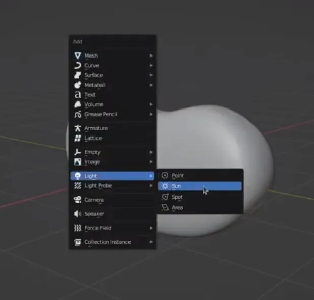
But first, a light needs to be added to the scene. We will use the Sun light, which provides a directional light that can be adjusted. To add the Sun light, press SHIFT+A while in Object mode and select Sun light from the context menu. If you’re still in Edit mode from earlier, simply press TAB again to exit Edit mode. To adjust the angle of the Sun light, select it and press R to rotate it to your desired angle.
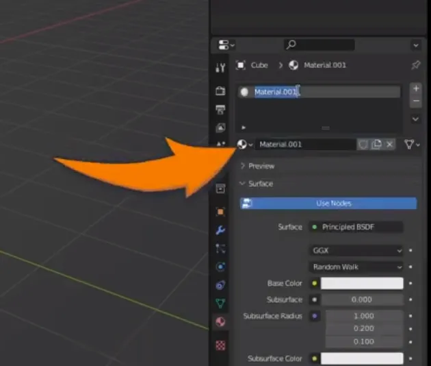
With the light added to the scene, the next thing to do is create a new material. Materials are containers for shaders that you can assign to 3D objects. A 3D object can have more than one material assigned, and it’s also possible to assign specific faces to use specific materials. To create a new material, click on the model and create a new material in the Material tab.
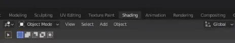
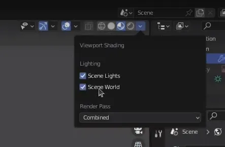
With the light and the material in place, it’s time to define how the shader works. Blender uses a node-based system for constructing shaders. It’s a pretty flexible tool, and it allows for consistent tweaking and iteration. To begin, click on the Shading tab at the top of the screen. This is a purpose-built view for working with shaders. However, you’ll notice that the lighting looks different here. Under Options, turned on Scene Light and Scene World to use the light you just added.
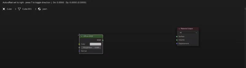
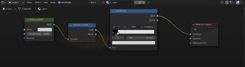
At a fundamental level, a toon shader uses what’s called a ColorRamp node to control the threshold of light on the material. In other words, the ColorRamp limits the number of shades of gray the light generates on the model, which is especially useful for getting that cartoony look. That being said, there’s a little bit of work that needs to be done beforehand. In the shader editor, delete the Principled BSDF node, as it’s not needed. Press SHIFT+A while searching “diffuse” to add a Diffuse BSDF. The Diffuse BSDF is a simpler base for our shader, which works well for non-photorealistic shaders.
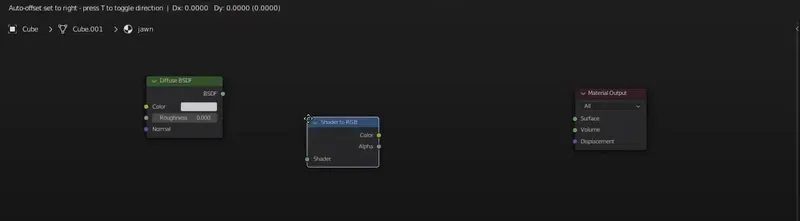
Next, add a Shader to RGB node using SHIFT+A like before. The Shader to RGB node is necessary in order to use the ColorRamp node, as it will take the shader output from the Diffuse BSDF node and turn it into RGB format. This also makes it easier to work with color transformations later on.
Now, add the ColorRamp node using SHIFT+A. Connect the nodes by clicking on the output dots and chaining them together like so. The trick to limiting the amount of shades with the ColorRamp node is to use the Constant type. Rather than using a gradient, the shader will use a hard cut between colors. Set up the handles like my example below. To quickly clarify, light projects a value between 0 and 255 on each surface of the mesh, based on the lights configured in the scene. For example, if a face is directly facing the light, it’ll be lit closer to the 255 value. Faces outside of the light will be closer to 0.
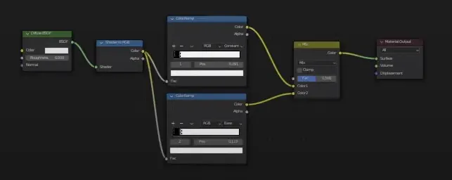
As a stylistic choice, I duplicated the ColorRamp node and also plugged the Shader to RGB node to it to mix in a bit of a gradient, but you don’t necessarily need to do this. This time, I changed the type to Ease and added a third black handle in the middle. To combine the two ColorRamp nodes, I added a MixRGB node with SHIFT+A and connected the two ColorRamp nodes in the Color1 and Color2 slots, while keeping the factor at 0.5.
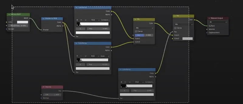
To create the rim light effect, we will use a Fresnel node in addition to another ColorRamp node to limit the output. A fresnel represents the rim light that appears on objects. For example, shining light on a metal ball or the light’s reflection on the water’s surface would be the fresnel effect. The fresnel works nicely to make the bean pop out a little more. Add a Fresnel node and a third ColorRamp node. Combine them with an additional MixRGB node by connecting the ColorRamp into the Factor, the existing shader output to Color1, and leaving Color2 as is.
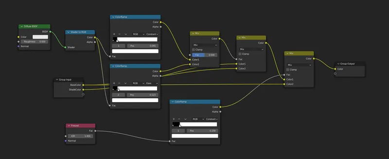
This completes the core toon shader. However, we can make the shader more accessible by making the color a parameter. That way, we could make a green material and a white copy of the material for the bean’s belly. To go about this, highlight all the nodes and press CTRL+G to group them. Open the Group panel with the N key and configure two inputs, a BaseColor and a ShadeColor, with the Color type. This allows the colors to be tweaked directly in the Material tab for the bean object. Next, add one more MixRGB node in between the two that are already there, and plug in the base and shade colors to convert the grayscale from the ColorRamp to the colors defined by the parameters. Finally, replace the Color2 on the last MixRGB node with the BaseColor to make the rim light the same color as the base color. The final shader node graph should look like this:
Making the Outline
It’s great that the bean looks cartoony now, but it’s missing a key visual component - the outline. There’s several ways to go about making outlines in 3D, such as using Blender’s Freestyle feature. However, I chose to use a method called the Inverse Hull method. The Inverse Hull method is used frequently in game engines, as the outline itself is 3D geometry and it’s much more efficient to use than a graphics post processor. Even though we’re rendering the images in Blender and we don’t need to worry about that efficiency gain, I still found this method to be the simplest overall. One downside however is that you’ll see artifacts sometimes between the mesh and the outline. Unfortunately, there’s no great way to avoid this other than make the outline smaller, but it’s not a bad tradeoff to make if you’re willing to accept how it looks.
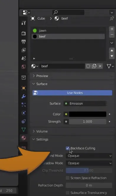
To create the outline, we will need to make another material. In the Material panel, add a new material. This time, switch the surface to Emission, which is just a generic color shader. You can do this directly in the Material panel, so you shouldn’t need to open the shader graph editor. Next, give it a black color and enable Backface Culling. Backface Culling is a property that allows the outline to display behind the model relative to the view. Otherwise, you would see a black color cover the entire model, and that’s not desirable.
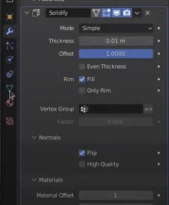
Lastly, the outline thickness itself is actually done using the Solidify modifier. Just like how you added the Subdivision Surface modifier before, go back to the Modifiers tab and select the Solidify modifier. Set the offset to 1, the normals to Flip, and the Material Offset to 1, so that the outline material is used for the outline instead of the base material. If you add more materials to the bean later, make sure to update the Material Offset so it points to the position where the outline material is in the list.
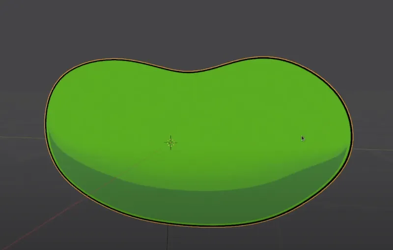
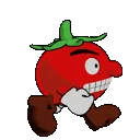
When all said and done, you should now have a nice outline like this!
Making a Basic Animation
This section is still in development. Stay tuned - it should be available soon!
Generating the Animation Image Files
Now’s the moment you’ve been waiting for - converting your 3D animation into a 2D sprite sheet for use in your games! Now you can use this method if you like to generate single images too, it’s really up to you. Before we begin though, let me give a quick word on sprite sheets.
Sprite Sheets
Sprite sheets are multiple frames of an animation combined into one image file. Sprite sheets are often used because making animations in game engines with multiple separate images is a tall order - not only do you need to manage all the frames in order, you also incur an I/O cost on the game engine to read multiple image files rather than just one. Sprite sheets are almost as old as video games themselves, it’s even common to see them used for tiles to make platforms and such.
Every modern game engine has the ability to handle sprite sheets. Flick! is made using the Godot Engine, so in Godot, I use the Sprite node and configure the number of frames to get the desired animation. This means that when you generate the sprite sheet, it’s important to stay consistent with the width and height of the sheet, so you know how many frames wide and tall the sheet is. Making changes later can be a hassle if you change the size of the sheet.
Some simple planning ahead of time can help mitigate this issue. Depending on your animation style and the number of animations you intend to have, you can roughly calculate how many frames you need. I would then reserve a decent amount of extra space, so you can add more frames later. For the bean animation we just made that’s 40 frames long, you will need at least enough space to fit 40 frames. Making a 6x6 sprite sheet isn’t enough, because that amounts to 36 total frames. Therefore, a good size would be something like 8x8, which gives us 64 frames to work with. If a frame is 128 pixels wide by 128 pixels tall, that yields a final image size of 1024 by 1024 pixels. When your game is almost finished, you can then trim down the sprite sheet to optimize the image, but don’t put that burden on yourself from the beginning.
Configuring the Camera
Without further ado, let’s see how we would go about making a sprite sheet with a 3D animation. The first step to making sprites at all is to configure a camera in your Blender scene, so there’s something to even render at all. With a camera, you can position the camera so the object is in view the way you like, and that’ll serve as the basis as the render. Add the camera to the scene using SHIFT+A.
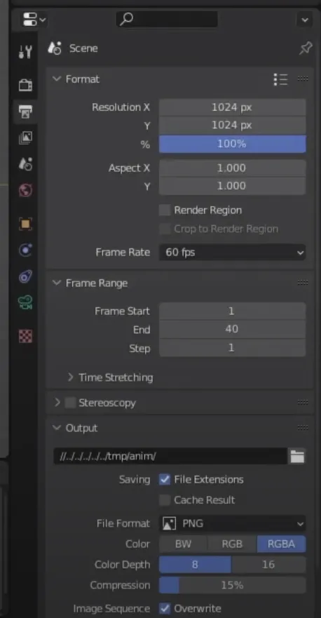
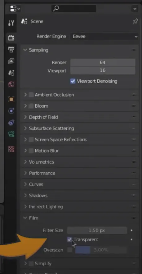
We will need to configure some of the camera’s properties to get the desired image result. In the Output Properties section, set the resolution to 1024x1024, or whatever you desire. Even if your target resolution is smaller, it’s not a bad idea to render it to a higher one for more fidelity, because ImageMagick can downscale the images for you when we create the sprite sheet later. Also, change the output directory so the rendered frames are in a location that can be referenced later. I like to render my animations to a /temp folder, but this can be wherever you prefer. I also recommend to change the file format in the Output Properties to “PNG” with RGBA colors. Next, check the Transparent setting under the Film section in the Render Properties panel. This ensures the rendered images have transparent backgrounds. Otherwise, the sprite will have a white background in the game engine, and that’s not desirable.
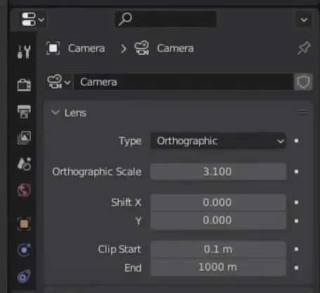
It may also be preferable to set the camera to Orthographic. Orthographic makes the sprite look more “2D”, but you can experiment with both Orthographic and Perspective modes to see what you like best. If you stick with Orthographic, make sure to adjust the Orthographic scale until the object fits the frame. It’s good to leave some space so the whole animation fits into the camera view.
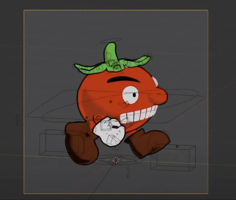
With the camera properly configured, use the G and R keys to move and rotate the camera so that the object is in the frame. You can use Numpad0 to test the camera view and adjust it accordingly. Make sure the entire animation fits in the camera frame and tweak until it does.
Rendering the Animation
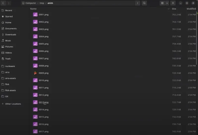
Now that you have the camera configured and the animation fits, it’s time to render! Before rendering animation frames, it’s a good idea to make sure there are no files in the output folder. While Blender will overwrite the files for you, if you change you animation to be less frames than it was previously, you run the risk of mixing frames with a previous render. When you’re ready, press CTRL+F12 to render the animation frames to the output directory. Depending on how complex your model is, it may take a little bit of time. Once it’s done, you’ll see all the frames are now rendered to the output directory!
Making the Sprite Sheet
However, we don’t have a sprite sheet yet. This is where ImageMagick comes in.
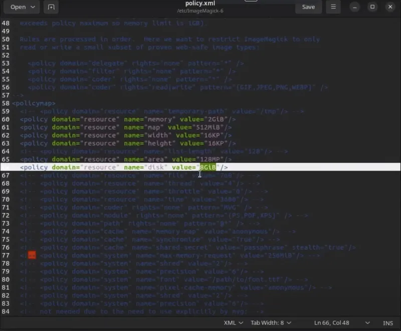
Right before we use ImageMagick, we need to configure it to have a higher memory cap. THIS IS VERY IMPORTANT. If you have long animations, ImageMagick will fail to combine all frames if it doesn’t have enough working memory, and its default setting is low. To do this, find the policy.xml file that is part of the installation. It’s located in the /etc/ImageMagick-6 folder on Linux machines and in the Program Files install directory on Windows machines. Change the memory line to at least 2GiB and the disk line to at least 8GiB. Don’t worry about it taking up storage space because of this - this is simply increasing the memory limits so ImageMagick is allowed to process more images in one go.
Now we can generate the sprite sheet. Open a Terminal or Command Prompt window, in the working directory where you would like to generate the sprite sheet image. The command we will be running looks like this:
magick montage * -geometry 128x128 -tile 16x16 -background transparent -filter Catrom spritesheet.pngOn Windows systems, you must prefix the command with “magick”, otherwise it will not work properly. This is not the case on Linux or Mac systems, as you can omit it.
The montage command is used for combining many images into one. It also has a lot of customizable options, which we will be using a few of them:
- The first argument is which images to use. An asterisk indicates to use all the images in the current working directory. To access your temp folder, use /temp/*
- Since I rendered the images to a higher resolution than my target, I’ll add a -geometry 128x128 argument. This’ll shrink down each frame to be that size. You can omit this if you rendered the individual frames to the desired size already.
- To control how the tiles are laid out, add the -tile argument. In your case, you will change this to something that will be inclusive of your entire animation. For example, if you have 40 frames in your animation, you can’t use 6x6 because that’s only 36 tiles.
- To preserve the transparent backgrounds, add -background transparent.
- And finally, if you’re shrinking down the frames, I recommend specifying a downscaling algorithm. Catrom applies a Bicubic filter, which looks pretty good in my experience. Add the -filter Catrom argument in this case.
- And lastly, specify the output image’s name.
The command should take a couple seconds, and then you’ll have a sprite sheet! Feel free to tweak these options as you see fit to get the result you’re looking for. If you run into errors, make sure your images argument and your output name arguments are correct.
Closing Thoughts
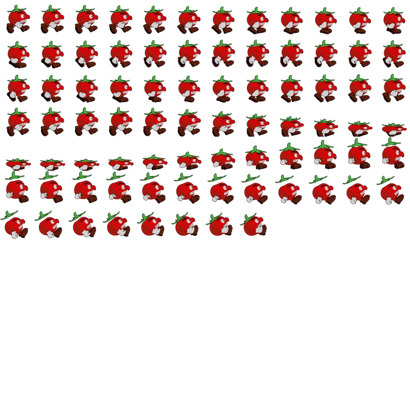
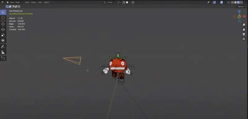
With it all said and done, your animation will look like this:
And that’s it! Now you have a beautiful sprite sheet for your 2D game. If you want to tweak your animation, I recommend saving this command to a script file, so you can run it as many times as you like. Because you chose 3D, it’s much easier to make animations because you have the rig to work with, and Blender can interpolate the in-between frames for you. It also really helps for characters that need to turn around in their animations.
Thank you and have a great day!