Complete 3D Game Character Creation Guide (From Blender to Godot)
This guide can help you get started making your own 3D characters for your Godot game from scratch!
I’m still working on getting images up on this guide, so stay tuned!
Summary
The goal of this article is to provide a cohesive workflow for making 3D game characters from scratch for your favorite game engine, explaining the tools and the rationale behind the use of the tools in certain scenarios.
- We will walk through the entire process of making a 3D model from scratch, including the modeling, rigging, texturing, and briefly through animation
- We will model the head, body, eyes, clothing and accessories for your character
- We will make an anime-like toon shader, as that’s what I used for my characters
- We will utilize a simple method for texturing anime style models that skips a lot of UV unwrapping work
- We will use custom normals for the face to make the shading look cleaner
- We will set up a Rigify rig that is compatible with both Mixamo and custom animations
- We will use shape keys as a method for controlling the character’s facial features
- We will export the finished model and import it into Godot
Prerequisites
- Blender 4.0 or higher
- Godot 4.2 or higher (or your game engine of choice, but I’ll only explain importing into Godot here)
- At least a basic understanding of Blender’s interface (you have at least opened the program before and navigated around)
Add-Ons
Blender provides the ability to extend its functionality through add-ons. As part of the workflow, I rely on a few of these addons to speed up the process. Here’s the list of add-ons that you may want to download prior to following this guide.
Pre-Installed Add-Ons
Blender comes with some add-ons pre-installed but they may not be enabled by default. I recommend enabling these add-ons:
- F2
- Rigify
External Add-Ons
To install these add-ons, download the ZIP file from the links provided. In Blender, select Edit > Preferences > Add-ons and click the Install button. Locate the ZIP file of the add-on you want to install it. Make sure to check the box to enable the add-on.
- Vertex Color Master: https://github.com/NoxelFoxel/blender_vertex_color_master
- Expy Kit: https://ballsandninjas.gumroad.com/l/xotibs
Intro
Bringing your characters to life for your dream game is a wonderful thing to do. However, the process of making a character is complicated, even more so if you have barely used Blender before. Even with many great tutorials out there, it’s challenging to develop a workflow that you can repeat consistently. That’s why I wanted to make this guide. My goal with this guide is twofold - to give you a cohesive workflow you can adapt to making your own characters, and to explain the tools that we will use and the reasoning behind why we apply them. I wouldn’t say this is a complete beginner’s guide, but I’ll do my best to explain it in a way any Blender newcomer can understand.
For some context, this guide is geared toward making 3D characters for video game purposes. While a lot of these principles apply to all forms of 3D work, such as for animation, making game characters demands more emphasis on optimization and workability. In addition, I’ll be using the Godot Engine as my target for the resulting 3D character, but that doesn’t mean you have to. You will find that every game engine uses a similar pipeline for importing characters from Blender, and you should be able to adapt the workflow to your specific engine needs.
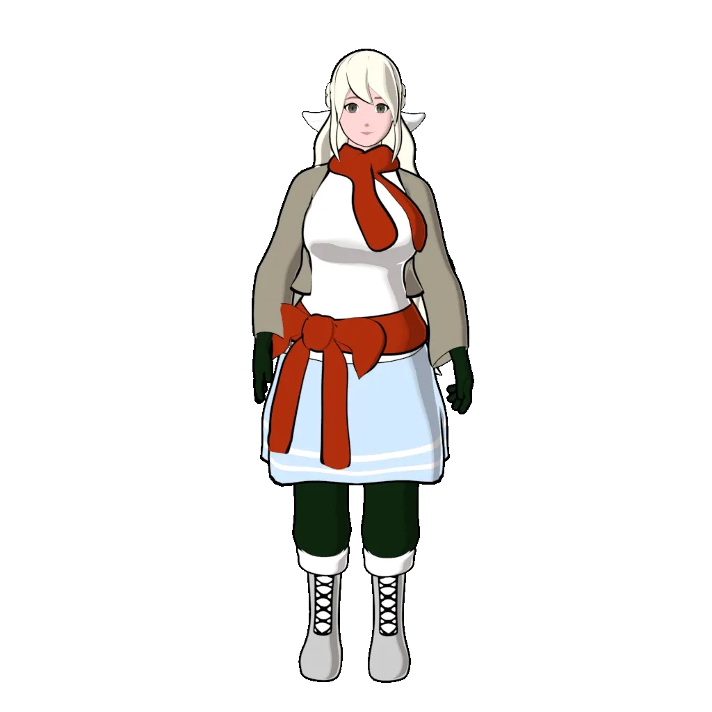
For additional context, I’d like you to meet Kaila. She’s one of the lead heroines in the game I’m making. I’ll be recreating her 3D model in this guide to show you the process, so don’t be alarmed by the imposter. Regardless, the process I used for both the original and the recreation is largely the same, except that I spent a longer amount of time making adjustments on the original.
Without further ado, let’s make preparations to build your 3D character!
Before We Begin…
Before we begin, let me mention what won’t be covered in this guide. I think it’s only fair so I don’t waste your time with something specific. There’s three things primarily - normal maps, texture painting and face rigs. The art style I’m using does not actually require the need for complex texturing, so I do not need to use normal maps or traditional texture painting. Regarding face rigs, I haven’t spent too much time in this area and I don’t really have much to show here. However, I will touch upon the use of shape keys to animate facial features briefly.
Let me also give you the high level of the workflow we will be learning how to use. The general 3D character pipeline goes like this: create reference images, model the base body, model the hair, model the clothing and accessories, clean up the model, UV unwrap and texture the model, add shading to the model, rig the model, animate the model, and finally export it for use in your game engine. The modeling part takes the longest in my experience, but once you do it once, you can reuse a lot of the pieces on other characters you plan to make. The rig is also fairly reusable, especially with Rigify, the tool we will be using once we cover it. With enough practice, you should be able to make an entire character in ten hours or less, but that also depends on the level of detail you’re striving for.
The next thing we should discuss is a little bit of pre-planning for your character. It’s not a bad idea to understand the medium you’re making the character for, so you can make design decisions that’ll save time. This will also help you determine how optimal your character needs to be, what kind of art style you want to use, and more. I have prepared a few questions you can ask yourself to aid you in this process.
- What’s your character’s role in your game?
- A main character will want to have more polygons because they will likely have the most screen time in your game. NPCs and some enemies can sacrifice some detail for performance without the player noticing too much of a difference.
- What platform(s) will my game be made for?
- Mobile and lower end hardware will require more optimization and may limit how many polygons you want to use. Mobile platforms also tend to have restrictions on lighting, so it’ll impact how your character looks between platforms. Games like Genshin Impact paint shadows on the textures of the character model to keep it looking stylish even on mobile.
- High end PCs and modern Playstation and Xbox consoles can handle much more polygons, generally speaking. From my research, an average AAA character model has 50,000 polygons, or triangles.
- What platforms do you intend to make your game for?
- How many instances of the character will appear on the screen at one time?
- If it’s one instance, such as the player character, then you have more leeway on how much detail the character can have.
- Games like the Dynasty Warriors series have to ultra-optimize the enemy models because there’s usually hundreds of them spawned on the screen at the same time.
- What kind of story or mood do you want your character to invoke?
- When will the character appear in the game?
- Will you need to share animations between characters?
In general, the more screen time your character has, the more detail you will need. You want your main character to stand out, right? In addition, targeting less powerful platforms such as mobile will limit how much detail you can use regarding total polygon count, so keep that in mind. If your character is going to appear in cutscenes as well, you could even make a higher fidelity cutscene version of your character and load that one at that time.
If you would like some further information, check out these YouTube Shorts I made on the topics:
References!
Creating the Reference Images
Let’s begin the process by procuring some reference images. If you have done modeling before or are familiar with some of the process, you’ve probably seen what’s called a character model sheet. This is one or more 2D drawn images that depict the character in a neutral pose from the front, side, and sometimes top views. You can model without them, but it makes things a heck of a lot easier if you have a reference. Typically, a concept artist would put this together and hand it off to the 3D artist, but if you’re doing the work yourself you’ll either need to make one of your own or find an existing one as a base for your character’s proportions. I understand that not all of us are good at drawing, but you’ll still be able to work with existing references.
Start by searching for existing model sheets on the internet that roughly match up with the character design you want to make. Focus primarily on the proportions - you will be using the reference largely for the base body modeling, so the clothing on the reference matters less. You can actually derive the clothing fairly easily later on by using cloth physics or just duplicating parts of the body. Lucky for me, there’s plenty of busty female reference sheets that I could use as a base for Kaila’s design.
If you do have the capability to draw, you can derive your character reference sheets from the aforementioned references. In a drawing app like Krita, start with the front view and use the reference as a guide to make your character drawing. I think it’s OK to trace a little here, as long as you’re only tracing the proportions and are not copying the entire design. On a separate layer, you can then add details of your character like the face, the hair and the clothing. Before moving to the side view, I recommend making yet another layer, and drawing straight lines from each important part of the body, such as the top of the head, the chin, the shoulders, etc. This ensures that your front and side views are going to be proportionate, and it’ll help a lot when you are modeling later on. Then you can draw the side view much the same way as the front view.
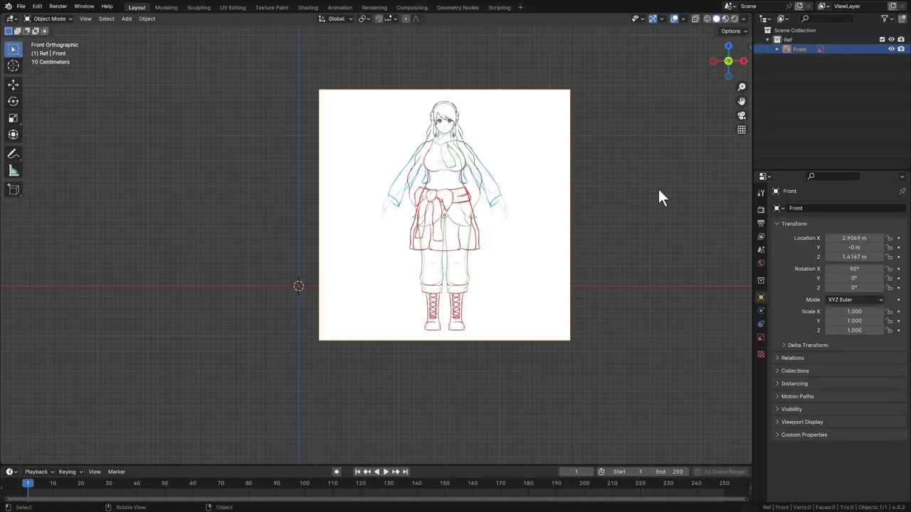
Once you’re done with your reference image, I prefer to export the front and side views as separate png files, but you can get away with having them both on the same image. I also highly recommend using a high resolution, such as 4K, so you can see most of the detail while zooming in when you’re working in Blender. Here, you can see the final reference images that I’ll be using for the modeling process. Note that there isn’t much detail - that’s actually fine because you will want the images to be clear enough that you can see what you’re doing while modeling.
Importing the Reference Images
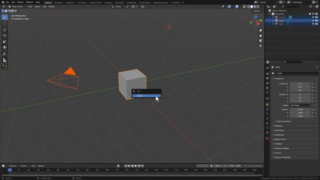
It is now time to import your references into Blender! Luckily, this is very simple. Open a new Blender scene and clear everything by pressing the A key to select all, and then X to delete them. We will add the light and cube later on when we need them. This way, we now can import the reference images with a clean slate.
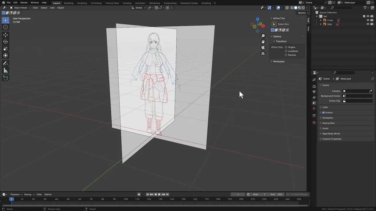
To start importing the reference images, set the camera view to the orthographic space of the reference image you plan to import. For example, to import the front image, set the camera to Front Orthographic view using the NUMPAD1 key. After that, drag the image from your file explorer into Blender, and Blender will import your reference image for you.
Orthographic view is a view that flattens all depth, effectively making it two-dimensional. The view is then restricted on two axes, such as the X and Z axes in the front orthographic view. The main use case for orthographic view is to adjust your 3D model to follow a reference image while you’re still building the foundation. It’s also very useful for hard surface modeling, such as making buildings. To switch to Orthographic view in Blender, use the NUMPAD1 key for the front, the NUMPAD3 key for the right, and the NUMPAD7 key for the top. To flip to the opposite side, hold CTRL while selecting the NUMPAD key of choice.
Perspective view, on the other hand, shows your 3D scene in actual 3D space, so you can rotate the view freely. You’ll spend a lot of time in this view making tweaks to your character, and it’s especially great for sculpting. Use the middle mouse button or NUMPAD5 to go into Perspective view. Lastly, keep in mind that not all references are made with orthographic view in mind, so I recommend checking your work in both views to make sure it looks good.
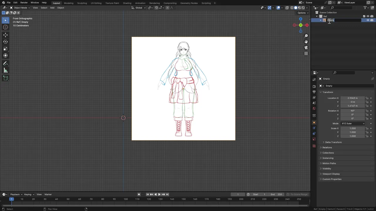
As you add references into your project, you may find that your Blender scene gets cluttered pretty quickly, so let’s clean that up a little here. I like to create a separate collection in the scene hierarchy just for the reference images, like in this example here. It’s also a good idea to name the reference images accordingly so you can identify them at a glance. Having all the references in the same collection is useful because you can hide all of them by clicking the eyeball icon next to the collection. To create a new Scene Collection, press the New Collection button in the top right corner of the screen, and then you can drag it in the hierarchy to where you want. Double-click or press F2 while the collection is highlighted to rename it.
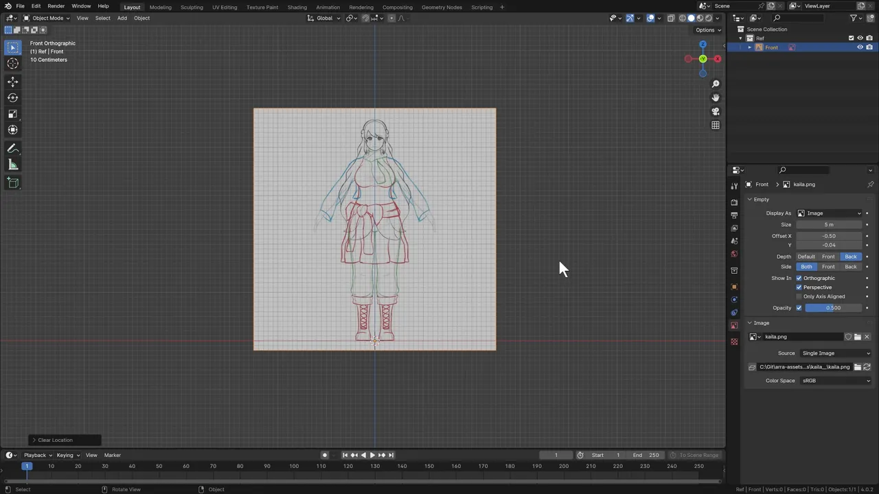
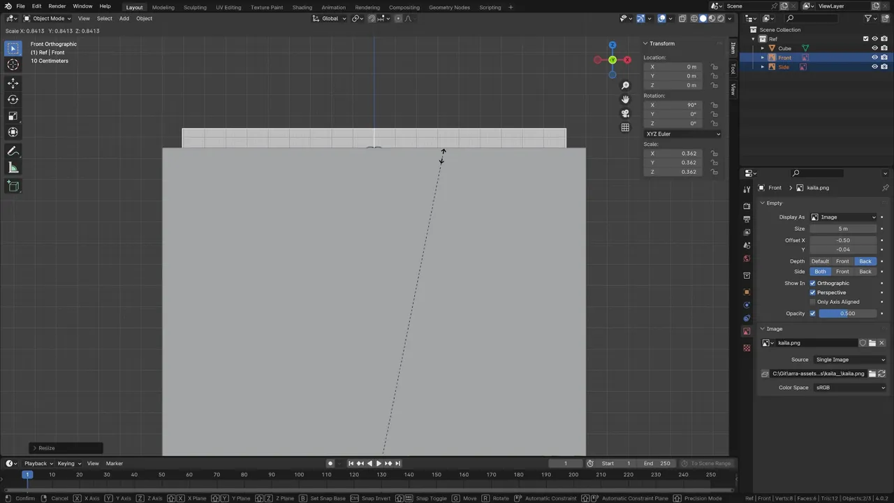
Now let’s tweak some settings on the reference image to make it more useful. With the reference selected, navigate to the Data tab at the bottom right corner of the screen. Tweak the Offset Y until the origin (the orange dot on the image) lines up with the bottom of the feet on the reference. We want to do this because it’ll be easier to scale the reference later and it also makes it easier to align the reference with the ground level. Additionally, adjust the Opacity setting to make it easier to see through your reference while modeling.
To reset the position of the reference image, press ALT+G to clear the location, placing the reference at the origin point. Since we moved the Offset Y earlier, it should now be aligned with the feet. Repeat the same steps to import your side reference image.
Before our reference images are ready to use, I like to use a little trick to get the proper scaling of the character on the reference. It’s a pain to realize later on that one of your characters is ten times bigger or smaller than the rest! Blender does, in fact, have a way to give you an actual measurement in real-world units for sizes of 3D models, but it doesn’t do this with reference images. Therefore, we will create a temporary cube, measure that, and then adjust our reference to about the size of the cube.
To create the cube, press SHIFT+A to bring up the Add menu, and select Mesh > Cube. We will need to move the cube such that its origin point is on the X axis exactly, so we can scale it properly. First, move the cube by pressing G to invoke the Grab (or Move) command. Since the Cube is exactly 2 units tall, if you press Z and then 1, it’ll move the cube up 1 unit on the Z axis, putting it exactly where we need it. Afterwards, we want to scale it from the bottom, so set its origin point by right-clicking, selecting Set Origin > Origin to 3D Cursor. With the cube now in place, type in the desired height of your character in the Dimensions field in the Transform panel, under the Z axis. If you do not see this panel, press the N key to hide or show it.
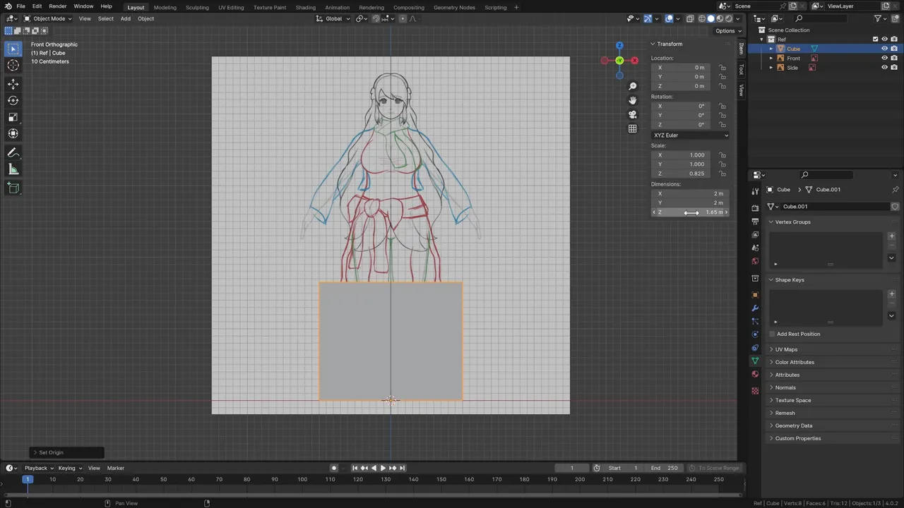
At this point, you can then scale the reference images so that the top of the head and the bottom of the feet are exactly as tall as the cube. Select both reference images and press the S key to scale the reference until the top of the head is roughly as tall as the cube. Once done, you may delete the temporary cube.
With the references in place, we may now start building the foundation of the model - the head!
Modeling the Head
There are two traditional ways to 3D model characters, one called polygon modeling and one called sculpting/retopologizing. Polygon modeling involves building your 3D character by adding and extending geometry and tweaking it repeatedly. Sculpting and retopologizing, on the other hand, focuses on making a base mesh and doing a lot of the work in Blender’s Sculpt Mode. Sculpting, however, results in immensely large polygon counts, so the retopology process effectively has the 3D artist rebuild the mesh while preserving as much detail as possible. The latter is great for more artistically inclined creators while the former is great for more technical creators. I’m using polygon modeling in this guide, not only because I am more comfortable with it, but also because it’s a good place to start with learning 3D modeling as it’ll teach you more of the core concepts. Both approaches take about the same amount of time all things considered, so you can’t go too wrong either way. If you’re more interested in learning sculpting, I have linked a great YouTube channel in the description that you can check out!
Another reason why I like polygon modeling is because it helps when making the head. It gives more control over the topology of the character from the beginning. In other words, topology refers to the layout of vertices, edges and faces on the model. It’s possible to have two very similar, if not identical looking 3D models with very different topologies. Think of it like cooking - you can make the same dish, but in very different ways. Generally speaking, good topology should allow the model to both be easy to work with, and should also allow it to deform more naturally. Typically, this means using mostly quads, or four sided faces, with a good edge flow. There will be times where we will break this rule, and I’ll make sure to explain why. Don’t sweat the small stuff here though - there’s many ways to make “correct” topology and all that matters in the end is that your model deforms cleanly when it’s animated.
The reason why I emphasize topology here is because the face in particular requires good topology flow on the eyes, nose and mouth. When we build the head, we are actually going to start by making the proper topology for the eyes, nose and mouth first. I have experimented with several approaches, but this was what I found worked best in my practice. We will make a vertex, add some modifiers and construct the loops together to form this shape. With the core edge loops, we will then adjust it in Right Orthographic view so it has a proper 3D shape. Then it’s actually not too difficult to fill in the rest of the head and neck from there.
Adding Your First Vertex
To begin, let’s create a single vertex. A vertex is one of the fundamental building blocks to a 3D model. Combined with edges, which are two connected vertices in a series, and faces, which are three or more connected vertices, these building blocks tell your computer how to render your character. We can then extend this vertex and create more to build the desired shape.
Unfortunately, Blender doesn’t have an option to add a single vertex built-in, but there’s a rather quick way to get down to just one. To start, create a cube just like before using SHIFT+A. Next, enter Edit Mode by pressing TAB so we can manipulate the geometry of the cube. For context, Blender operates in several different modes, which offer different tool sets for each. Object Mode and Edit Mode are the most common, but there’s also Sculpt Mode, Pose Mode and Weight Paint Mode we will touch on later. While in Edit Mode, press A to select all eight vertices of the cube, and then press M and choose the At Center option to merge them together into a single vertex.
If you want to see a quicker way to add a single vertex in Blender, I made a YouTube short which I’ll link here so you can check it out later!
If, at any point you find it difficult to see the vertices in the Blender view, you can adjust the visual size of them. Navigate to Edit > Preferences, and then find the Vertex option in the Themes > 3D Viewport settings. I like to set it to 6 pixels, but feel free to adjust this to your liking. I also made a separate YouTube short explaining this further.
Adding Mirror and Subdivision Surface Modifiers
Before constructing the head, let’s add a Mirror modifier and a Subdivision Surface modifier to the vertex. Modifiers in Blender are configurations that are applied to an object that affect geometry or data. The Mirror modifier effectively duplicates your geometry to the opposite side while you work, saving you tons of time. The Subdivision Surface modifier adds additional geometry to your model by cutting each face in half. The idea behind it is to give your model a more pleasant and smooth shape while you model it in a low poly way. Be careful though, too many subdivisions will increase your poly count quite fast, so sticking with one layer of subdivision here is recommended.
- To add a Mirror modifier to the vertex, navigate to the Modifiers tab, which is on the right hand side of Blender’s default layout. Here, you can click the Add Modifier button, and search for the Mirror modifier there. You may not immediately see any difference yet, but if you hit the View in Edit Mode button on the Mirror modifier itself, you will be able to see the other side when you are modeling. You may even prefer the On Cage setting, which will show the other side with the vertices, edges or faces. Make sure to check the box under “Clipping” for now - this will prevent the vertex from traveling to the other side of the mirror, which is convenient in many cases. We will enable and disable Clipping periodically as we go.
- Add the Subdivision Surface modifier the same way, this time searching for “subdivision”. The defaults should be good here - the Catmull Clark algorithm smooths out the mesh for you, which is desired most of the time. Also, make sure that the subdivision surface modifier is after the mirror modifier in the stack. The order the modifiers are in DOES matter, but you can drag them up and down to sort them and see how it affects your model.
The Core Loops
Now we can start making the core face loops.
- Make sure your references are visible and that you are in Edit Mode with your vertex selected. Move the vertex with G so that it rests just slightly below the mouth, similar to what I have. To start making the mouth loop, first disable Clipping on the Mirror modifier, and then press E to extrude from the existing vertex. The Extrude tool creates vertices or faces by extending the model from where you extrude from. This is a very common way to build models. You may now turn Clipping back on to help with completing the loop. Repeat the extrusion to get a shape roughly like I have here. It’s not required, but I recommend trying to use the exact same amount of vertices I use here because it’ll make it easier to follow along, at least for the beginning stages.
- Next, select the entire loop with A and press E and then S to extrude and scale them outwards. Select and move each vertex with G to get something similar to what I have. We want the mouth to be a bit flatter at the top so we can extrude from there to make the nose. After that, select the inner loop by holding ALT and clicking on it, and then extrude and scale again to make the inner part of the mouth. Adjust it like before.
- Just a head’s up, I tend to adjust A LOT between steps, so if the model in my example looks different, just assume I moved around vertices. You also don’t need to follow the reference or my work exactly either. Modeling is an art, not a science, so you’ll have plenty of time to make tweaks as you build your character.
- After making the mouth, we will work our way up to the eyes, mostly skipping the nose for now. We will extrude from the side view of the nose later. Start by selecting the top two vertices on the mouth loop, and extruding up to where the nose is on the reference. Extrude straight up another time, up to the bottom of the eye level. Extrude once more to the top of the eye level as shown here.
- To make the eye loop, select the vertices directly to the right from where we extruded last, and make one more extrusion to the end of the eyelash to cover the eye. Select the new rectangle and make an inset by using the Inset tool with I, or by pressing E followed by S to extrude and scale inside. Now, use the Loop Cut and Slide tool with CTRL+R and create loop cuts both horizontally and vertically on the eye rectangle. The Loop Cut and Slide tool is also a very commonly used tool for extending geometry in Edit Mode, as it allows you to bisect faces. The tool also allows you to make more than one loop cut if you scroll up on the mouse wheel, and it also allows you to reposition the loop cut as well. However, we want these loop cuts to be directly in the middle, so just pressing the key and placing the loops is enough. Select the middle vertex in the eye rectangle and press X to delete it. We want there to be a hole here so we can make an eye socket later. To finish up the eye, repeat the process of selecting the vertices and moving them to roughly match the reference. If you’re following along with me, your eye loop should have eight vertices on each layer.
The Side of the Head
We are going to now take our loops and line them up from the side view so they match the contours of the head.
- Switch to Right Orthographic view with NUMPAD3 and select all the vertices with A. Now move the vertices directly to the left so the bottom aligns roughly with the chin. For the nose, click the middle mouse button to rotate the view a little bit so you can see and select the face where the nose should be. To make it easier to select, you can press 3, not NUMPAD 3 on your keyboard to go into Face select mode. For reference, 1 is for Vertex select and 2 is for Edge select modes. With the nose face selected, return to Right Orthographic view and extrude it such that it reaches the tip of the nose. Of course, we don’t want the nose to be blocky, so go ahead and tweak the vertices on the right side of the nose more to the inside. Add two loop cuts as shown to give yourself more geometry to work with while you adjust the shape.
- Next, let’s adjust the eyes so that they line up with the side view. Select both the outer and inner eye loop, and move them up to the front of the eye as shown. We will want to add some curvature to the eyes, which we can do from the top view. While we don’t have a top view reference, it’s not too terribly difficult to estimate the shape without one. With only the inner eye loop selected, press NUMPAD7 to enter Top Orthographic view, and press R and then - 15 to rotate it fifteen degrees inward. Move the eye loop back a bit so it remains inside, and adjust the vertices to give it a bit of curvature. Once done with that, return to the side view and move the end of the eye loop just past the eye reference. Adjust the inside vertices as well to match the reference as closely as you can. One by one, work your way to the tip of the mouth and move each vertex back a bit to form the smile. While you are there, move the outermost vertices as well so they are a bit closer to where the cheeks will be.
- To finish up this portion of the process, go one by one with each of the middle vertices and align them such that the model, not the vertices, are aligned with the reference. Due to the Subdivision Surface modifier, the model is going to shrink down just a bit, especially when vertices are further apart from each other. To make sure you can see the resulting model while you’re editing, click on the Edit Mode button on the Subdivision Surface modifier in the Modifiers panel. This will make it much easier. Notice how I moved the vertices where the bridge of the nose is pretty far past the reference, but the model still lines up with the reference. Repeat this for the rest of the nose and around the front of the mouth too, but just for the front vertices. We can very easily get the rest to line up for us, such as the middle mouth loop, by using the Smooth Vertices tool. The Smooth Vertices tool averages the position of the selected vertices with adjacent ones, effectively smoothing the position. You can find the Smooth Vertices tool in Vertex > Smooth Vertices. I use this tool all the time, so I mapped it to the D key which you can do by right-clicking the menu option and assigning a shortcut from there. Now, simply select the areas you want to smooth, such as the middle mouth loop, and press D to smooth it out relative to the inside and outside loops. You can repeat this as much as you desire.
- Use the middle mouse wheel to orbit around your model to check your progress so far. You should now have a face mask that’s correctly following the face shape! Of course, feel free to tweak it as much as needed until you are happy with the shape.
The Jaw
With the core loops done, it’s now time to fill in the rest of the face, going up to the jaw.
- From the front view, select the three outside vertices on the nose like I did here, and extrude them up to where the adjacent vertices on the eye loop are. After that, select the edges that were not extruded and pressFto create faces to fill them in. Repeat the process one more time to fill the faces up to the edge of the face mask. I know there’s other ways to fill in faces, such as using the Grid Fill tool, but I tend to be more comfortable doing it this way. Feel free to fill in the faces with the method most comfortable to you.
- Thankfully, completing the rest of the jaw is pretty straightforward. Select the entire outer edge loop, which should go all the way around the head now. Extrude and scale a new loop, and move it out so that it’s following the chin on the reference. This time, adjust the loop so that the top of the head is flat and that the cheek is making a straight line down the side. Repeat this process another time, making sure it’s aligned with the chin from the bottom.
- You may notice from the front view that the face looks too thin. To fix this, grab two vertices at a time from the loops we just created and adjust them to match the front view reference. To finish up the jaw, extrude another time from the outside loop like before, and adjust it to match the reference. The result so far should be from the jaw up to the ear.
- I made one little tweak near the top of the eye by using the Knife tool to add a bit more geometry to the top of the head. This is because I wanted to make it a bit rounder from the top view and having the extra vertices help. Notice I made a triangle here too. You may have heard from other Blender videos to avoid making triangles at all costs, but I find this is not always necessary. The main reason why quads are preferred is because it’s much easier to work with quads while modeling. Therefore, my recommendation is to use quads as much as you can, but don’t sweat it if you have a few triangles here and there.
The Neck and Back of the Head
To wrap up the head, we now need to create the neck and the back of the head.
- Before we can do that, rotate the view to the bottom of your head and adjust the bottom most chin vertices to be aligned with the back of the jaw. When extruding earlier, this part may have not moved correctly so it’s a good idea to fix it now. I also adjusted these vertices from the front to round it out a bit more with the reference.
- Now, it’ll be much easier to complete the back of the head. Select the edge loop of the back of your face mask and make an extrusion up to the back of the neck on your reference. Scale it down a bit so the top of the head is still roughly flat, and add a loop cut in the middle of the extrusion. The loop cut will help later when we make the body and the ears.
- To make the neck, start by selecting the faces where the base of the neck would be, and extrude down about halfway. I like to level out the extruded part here so it’s more even. Press S, Z, then 0, to do this, and then rotate it to match the reference. Extrude one more time to the bottom of the neck and scale it accordingly.
- For the back of the head, select all the edges from the top to the base of the neck, excluding one. Similar to how we filled in the faces earlier for the front of the head, I like to exclude one so I can fill it in manually after making extrusions. If you were to extrude every edge here, it would be more cumbersome to merge the vertices with the ones below in my opinion. With all but one edge selected on the back of the head, extrude and pull the edges to the middle of the head until it gets stopped by the Mirror modifier’s clipping.
- However, you may notice a problem here. The back of the head has no edge loops, but the neck has two. This means we wouldn’t be able to make even quads if we filled in the remaining face. To fix this, first dissolve the one edge on the back of the neck and add a loop cut on the back of the head so the loop count matches. We don’t need the extra loop on the back of the neck, so it’s safe to remove it. Now you can fill in the rest by selecting the empty edge and pressingFtwice. Just like before, adjust the shape of the back of the head and the neck as you see fit.
- To wrap up here, select the edges between the jaw and the neck and add an edge crease to it with SHIFT+E, and then enter 1. Edge creases are a tool that allows the subdivision surface modifier to respect the sharpness of an edge while smoothing your model. I like to use this for areas such as these that will be sharper. We needed to enter 1 because edge creases operate on a scale of 0 and 1. If you ever wanted to remove an edge crease later on, press SHIFT+E, and then -1.
The Ears
I tend to forget about the ears a lot, so much so that I recorded the whole section on the body without ears on the model. Don’t worry though, I listened to myself and recorded this bit so you can still learn how to make ears.
- All you need to do here is locate the vertex where the ear should be and delete it. Typically, it’s going to be on the edge loop right where the jaw ends and meets with the neck.
- With the resulting hole, select the edge loop and extrude and scale down to create the base of the ear loop. Scale it on the Y axis or tweak the vertices to shape it around the reference.
- After that, return to the front view and make a few extrusions out to shape the ear.
- Close the last loop manually by selecting pairs of vertices and pressing F to fill in faces.
- Rotate the ear from the top view to face out a little bit as needed.
- And to finish off the ear, go ahead and add an edge crease right on the first loop connected to the head.
- If you want to make an indent on the ear, select the faces on the inside of the ear and inset them, then move the insetted faces slightly inside. I don’t think it really makes much of a difference in my case, but maybe you want to add a bit more detail to your characters’ ears.
With that, you now have a head! Awesome job so far! If you have any questions, please don’t hesitate to use the comments section here - I’ll do my best to answer!
Modeling the Facial Features
Now it’s time to move on to the facial features! Given I’m using an anime inspired style, there’s some key differences you’ll see here on my model that you may not see on other models. Those differences mostly come down to how the facial features are structured, such as the eyes and the eyebrows. More traditional 3D characters will use spheres and textures to make the eyeballs, but we can get away with just a circle for the anime eyes. This is largely due to the fact that the shading is flat, so the inside of the eye itself doesn’t really matter that much.
The Eye and Mouth Sockets
We are going to start by making the eye and mouth sockets. The purpose of these sockets is to provide background for the eye and the mouth, as we don’t want the player to be able to see directly inside the character’s head. Plus, this gives us the opportunity to add white eyes and black for the inside of the mouth.
- Start by selecting the edge loop where the eye is, and extruding on the Y axis inside. Scale it up a bit so the opening has more room to work with.
- Add one or two more extrusions, working your way inward and scaling down to make a somewhat rounded shape.
- You can simply cap off the end of the eye by pressing F to fill here because the topology here doesn’t matter. The eyes will animate later on, but the eye socket doesn’t need to.
- The mouth socket can be made much the same way, so go ahead and start by selecting the mouth loop and extruding it inwards. Due to the awkwardness of the mouth shape, you may not get a desired result just by scaling it up or down, so you may need to manually move around vertices to get the shape you want.
- Before closing the mouth, it helps to have another edge loop that’s creased near the opening so that the mouth keeps its shape better. Add an edge loop with CTRL+R, slide it by pressing G twice and then crease it with SHIFT+E. All that matters here is that the mouth socket has some space for the mouth to move. Now you can close the mouth loop in much the same way.
- Once you’re done, I recommend selecting the initial eye loop and mouth loops and marking seams. When we UV map later, these seams will tell Blender to separate these parts so we can move them to different parts of the image texture. This can be done by pressing U to bring up the UV options, and then selecting Mark Seam.
The Eyelashes
- To make the eyelashes, start by selecting the opening loop on the eye, this time extruding and scaling outside the eye. Remove the second seam that it creates by pressing U and Clear Seam.
- Next, move each vertex of the eyelash to roughly follow the reference. It’s useful here to snap the vertices to the contour of the eye during this process. To do that, enable Snapping with the button up here, and choose the Face Project option. When you move the eyelash vertices, Blender will snap it to the closest face, which is the head in this case. Disable snapping once you’re done.
- From the side, select the eyelash edge loop and move it out just a bit to give it some space from the head.
- To make the part that flares out, just select the two vertices around there and extrude it out a bit.
- If your character has space between eyelashes, you can remove it simply by selecting that area and using X to delete the face. I like to slide the remaining vertices down closer to the eye socket as well.
The Eyebrows
The eyebrows can be made very simply with a flat mesh that follows the reference and snaps to the head. It’s true that you could also draw the eyebrows on when you texture your character, but I think having modeled eyebrows work better when it comes to facial animations.
- Start by taking any edge or face on the head and duplicating it. Extrude it if necessary to create a face, and then separate it by selection from the head using the P key. Having the eyebrows separate for now makes it a bit easier to work with.
- Next, shape your eyebrow to the reference and extrude as many times as you need.
- Enable snapping once again with Face Project on, and with the whole eyebrow selected, press G and left click to snap it.
- Since the eyebrow may not have the same number of vertical edges as the head, you may see that some of the eyebrow is inside the head. It’s no big deal if you move the entire eyebrow out just slightly as it will not make any difference in practice. Holding SHIFT while moving allows you to move more precisely, which may be helpful to you.
The Eyes
Now that we have the eyelashes and the eyebrows, we can make the eyes. Like mentioned earlier, we don’t need to use a sphere to make a full eye. Instead, we will start with a Circle and add the details to it.
- Go into Object Mode and use SHIFT+A to add a Circle. Add a Mirror modifier to it as well.
- In Edit Mode, rotate the Circle 90 degrees on the X axis and then scale it down a bit.
- Line it up with the eye socket on the reference from the front, scaling and moving it as needed. Make sure to also move the eye on the side view in place.
- As you will see here, I use a combination of extrusion and loop cuts to model out the details on the eye. This is because of the UV and texturing method I chose, which will make more sense when we get to that point. More traditionally though, you would simply fill the circle in without doing this and would instead draw the details of the eye on a texture. Don’t worry too much about adding additional vertices here because it’s not going to be enough to incur a performance cost in the long run. Also make sure to fill in the face where the pupil is if you choose to follow along with me.
- It’s also a good idea to mark some seams on the various color regions of the eye, such as how I am doing here, as this will make coloring the eye much easier later on.
- Finally, rotate the eye about 15 degrees from the side view, and then move the pupil forward with proportional editing to give it some roundness. This way the iris is visible from the side view as well as the front.
Eye-Shines
It’s very common for anime inspired characters to have some sort of white eye-shine on the eyes. Funny enough, I experimented a lot with this when working on Kaila’s character design, but felt like her eyes looked better without them at all.
In this case, I’ll refer you to the Short I made on this topic to save some time here. Feel free to use that as well as the source video I learned it from to make your eye-shines.
Congrats on finishing the head and face! Next, we will tackle the body.
Modeling the Body
It’s often a good idea in 3D character modeling to actually model the character’s body without any clothes on. It may be jarring, but it’s plenty natural to do this in any form of art. It just makes it easier to add clothes later on, and it may even be required for your game if you want to offer customization options. At least this way, it gives us an opportunity to focus on the topology for the limbs. There’s not a whole lot of new concepts to introduce here, so I’ll go a little bit faster through this part. The majority of the process of building the body is simply following the reference, building and adjusting as usual.
The Torso
We will start with making the torso by extending from the neck.
- First, delete the hole on the neck by selecting the bottom middle vertices. Having this hole here will help later on when we make the legs.
- Next, use the Knife tool to make a cut right before the neck so we can dissolve one of the front edges on the neck. This allows us to have an even amount of vertices on the neck loop between the front and the back, making it easier and more consistent. The triangle here won’t make any difference with deformation, so don’t worry about it.
- Select the bottom edge loop and extrude, and then scale down to about the base of the shoulders.
- Overlaying the mesh with a wireframe may be helpful to you as you model.
- Extrude down about halfway down the chest, right past the armpits.
- Before extruding down further, select these two faces on the rightmost side and extrude them up to right before the shoulders. Add an additional loop cut around the armpits, and delete the extra vertex on the bottom here.
- Now, extrude down to the crotch, shaping out the hips in the process.
- From the side view, select the pairs of vertices and line them up with the reference. You can press the middle mouse wheel while moving to restrict to the Y axis.
- Lastly, round out the torso on the side a bit so it’s not so blocky. Smoothing or moving this middle loop will help.
The Crotch, Legs and Knees
Next, we will make the crotch, the legs and the knees. One thing you will want to know here is that we can use a special type of topology for joints such as the knees. If we inset the front face where the knee is and make knife cuts to reduce the geometry on the back, we will get something that both deforms well and keeps the rounded shape of the knee when it bends. We will use this technique later for the shoulders and elbows too.
- To start on the crotch, move the bottom vertices a bit closer so we can have them more even when we make the legs.
- Select the center edges on both the front and the back here and press F to fill in the faces. Add a loop cut with three loop cuts so it matches up with the number of vertices on the other side of the hip. Scale down the crotch on the X axis to give yourself more leg room. If you’re following along with me, your leg opening loop should have 10 vertices.
- Next, we will round out the opening here so the legs do not have an awkward shape when we extrude them. The To Sphere tool can be helpful here, but you may need to disable clipping if your character is extra thicc.
- Select the loop and extrude it down very slightly. Scale to zero on the Z axis to flatten it.
- Double check to make sure the circular shape is preserved and make manual adjustments if you have to.
- Once you’re happy with the shape, extrude down a couple times to complete the legs, stopping around the knees and the right before the feet. Scale and move the loops to match the reference, and add some more loop cuts if you need more vertices to work with.
- To make the knee caps, select the edge loop where the knee is and bevel it with CTRL+B. Inset the faces on the knee, then use the Knife tool to make cuts on both sides like this. Lastly, select the middle edge and dissolve it using X > Dissolve Edges.
The Feet
As for the feet, there’s no need to model the toes if your character will never show them, so I’ll just model the feet like the boot here.
- Start by extruding all the way down to the bottom of the foot from where we left off on the leg.
- Create two more loop cuts and shape the heel from the side.
- While in X-Ray mode, select the three sets of vertices from the front of the foot and extrude to the end of the foot. Add some loop cuts as necessary and shape the foot around the reference. Delete any faces on the bottom for now - we will reconstruct the bottom shortly.
- From the front, scale the vertices and edges on the X axis to match the reference. Shape the rest of the foot to the best of your ability.
- Select the edge right before the gap and repeatedly press F to close the faces. If you used the same amount of vertices I did, it should close up just fine.
- To finish the boot foot, create edge creases where the heel is, as well as around the perimeter of the sole.
The Shoulders, Arms and Elbows
To make the arm, we will make a hole on the torso where the shoulder starts and extrude down, similar to how we made the legs. Just like the knees, the shoulders and elbows will have a similar topology structure involving an inset and knife tool cuts.
- Navigate to where the shoulder would be on your model and you should see roughly six vertices shaped in a rough circle. Delete the middle edge to open it up and then round out the opening either manually or with the To Sphere tool.
- Realign the shoulder with the reference. I recommend scaling the X axis to zero here to make it a bit easier to work with.
- Extrude from the circle down to right to where the shoulder ends, rotating it if necessary to follow the arm. Add a loop cut in the middle of the shoulder and adjust it as needed. Typically it’s much easier to make arms with a reference in a T pose, but it’s still doable here.
- From the top of the shoulder, select the four faces and inset them just like we made the knee. Make knife cuts in a similar fashion on the front and back sides and dissolve the middle loop.
- Extrude to the elbow and once again to right before the hand. Add additional loop cuts as needed to follow the reference, but not too many.
- Repeat the process we used for the knee and the shoulder on the elbow. Select the elbow loop, bevel it, then inset the two faces on the elbow. Make knife cuts and dissolve the outer edge.
- Finally, make tweaks as best you can. The arm should be fairly evenly sized from the side view, which I’m adjusting here. Scale on the Y axis as needed.
The Hands
The hand is probably one of the most complex pieces to make. Being notoriously bad at drawing hands, I found that it’s really helpful here to find a top view reference of a hand on the internet and then model around it. We will actually model the hand separately from the model and then attach it once we’re happy with it.
- Find a hand reference as mentioned before and import it into the Blender scene. You can use the one I used - the link’s in the description.
- Select the edge loop where the arm ends and duplicate it. Scale it to zero on the X axis and separate it from the model with P > Selection.
- From the side, flatten out the left and right edges and move the bottom one in a bit. This helps a little to make sure the hand’s shape isn’t too awkward as we build it.
- Return to the top view and extrude out once. Line up the extrusion with the palm right before the knuckles. I highly recommend using X-Ray view here so when you box-select the vertices you want to edit, it selects the ones behind as well. Extrude again and shape it right before the fingers.
- You only have three verts on the top to work with but four fingers, so use the knife tool to make some extra to work with. Make sure to repeat on the bottom of the hand as well. Again, the triangles here are not going to be too much of an issue.
- Box-select the two, but actually four vertices making each finger and extrude it out a bit.
- At this time, you can fill in the missing faces on the side of the fingers by selecting the edge on the index finger and pressing F repeatedly until all the faces are closed.
- For each finger, make loop cuts right near the bases so the fingers aren’t so close together.
- Extrude the rest of the fingers to their tips and scale them so they match up with the reference.
- Make one more loop cut on each finger so that it’s split into thirds. This will help with rigging later and helps with shaping the fingers now. Bevel each of the middle loops as that extra resolution will help with the finger deformations as well.
- If you look at the hand now, you may find that the fingers are weirdly shaped and scaled. To fix this, select the bottom faces and scale them in a bit. You can also move them up and down as needed to give them the proper thickness.
- Add one more edge loop around the side of the hand and scale it out to give the hand some roundness.
- To make the thumb, select the two faces where the thumb would be and extrude out a bit. The thumb bends so you’ll have to move the vertices from the top a bit to angle it in more.
- Make another extrusion, and scale and rotate it once again so it lines up right before the finger part. Extrude two more times to complete the finger of the thumb.
- Just like before, bevel the two loops here for better mesh deformation.
- Clean up the look of the hand by smoothing vertices and resizing the fingers. The hand should be thicker from the top and gets thinner as it approaches the fingers. It’s handy to use your own hand as reference.
- To attach the hands, select the hand and then the model in Object Mode and press CTRL+J to join them. Rotate the hands to be aligned with the arms.
- The hand will not have the exact same amount of vertices on the opening edge as the arm does, but that’s OK. We will connect them manually. Select the bottom two edges like this, and press F to fill in the faces. Repeat this on the top too. Connect the resulting edges by selecting the face from the sides and filling from there.
- Smooth the edge loop connecting the hand and make any final adjustments you want to make the hand fit better on the arm. Leave the hand flat.
The Breasts
I wasn’t sure if I should cover how to make breasts in this guide, but in the spirit of completeness, I will. It may even be the reason why you clicked on this video in the first place. Anyway, breasts are surprisingly finicky in 3D modeling, especially for characters as well endowed as Kaila is. In practice, the breasts tend to look bigger once they are modeled in 3D, so you don’t have to follow your reference exactly if it feels like too much. Otherwise, the process is fairly straightforward.
- Start by deleting the two edges on the middle of the chest to make an open circle.
- If your character is thicc with several c’s, you may need to disable clipping on the mirror modifier. Extrude a bit on an angle. Also take a moment to round out the opening.
- Extrude two more times, or do what I do here and extrude and make an edge loop. Just make sure to extrude to the tip of the breasts on the reference.
- From the front, move the edge loops such that they match your reference. Double check that the breasts look the way you want in Perspective view as well.
- Before closing the breasts, make one more extrusion and use proportional editing to move it down and to the right a bit.
- To close the breasts, extrude and scale one more time, then press M and merge the vertices at the center.
- Tweak the shape to your liking. Notice I ignore my reference on the side a bit because it wasn’t really that accurate anyway.
- Add an edge crease at the bottom of the breasts going up to the armpit
- Make sure to re-enable clipping once you’re done and close the central chest area that may have been split.
- If you want more resolution so the breasts look less blocky, you can make cuts like I did here with the Knife tool, going up to the middle. I did this on the bottom where it was more noticeable. Add loop cuts on each face that was cut by the knife tool and close it again with the Knife tool in the center.
The Buttocks
For posterior’s sake, I’ll cover how you can make a butt on your character. It’s not super necessary if there will be some sort of skirt covering it up, but your character may require more prominent glutes if they are wearing skin-tight outfits or something. I’m just here to teach you 3D modeling - it’s up to you how you choose to use this information.
- On the behind, select these six faces and make an inset.
- Smooth it a bit then make it a bit rounder by adjusting the vertices and edges.
- Move it from the side as well to match your reference better. Here I move the leg in a bit and the butt a bit over the legs. Continue to smooth a bit and round it out as necessary.
- Create an edge crease on the bottom edges as well as the crack, then move the crack in a bit to make it more creased.
- If you need more resolution on the butt, you can always make a second or even third inset where we placed the original one.
With all that, the body is now complete… ly naked. It’s going to stay that way for just a bit longer, because we are going to make the hair next.
Modeling The Hair
Now that you have a body, it’s time to make the hair. The hair is another part that differs for stylized characters over more realistic ones in that it’s much more blocky and less detailed. Typically, realistic hair would be done using Blender’s hair particle system or by using a combination of warped planes and textures, but we are going to use a technique that’s common for anime style hair. Blender has a curves system that allows you to make geometry using bezier curves, in which you can control the shape and angle of the curves. You also have the ability to define a bevel curve, which we can use to our advantage to give the curve a hair-like shape. Once we’re done making the hair strands with curves, we can then convert it to a mesh and work with it that way. This technique is often used over modeling the hair directly because it gives you more control over fine strands.
The Bangs
We will start with making the bangs, the hair strands on the front of the head. It’s easiest if you can visualize the hair as separate parts. In this case, I can represent Kaila’s bangs as three separate pieces.
- In object mode, press SHIFT+A and add a Bezier curve.
- In the curve properties tab, lower the resolution preview down to a number such as 4, this way we don’t create too many polygons with the hair.
- Add one more curve, this time a circle, and use that as your bevel object. With the original Bezier curve selected, select the circle as the bevel object.
- Select the circle again and reduce the resolution preview to 1 so it doesn’t produce too many polygons. Scale down the circle in Edit Mode and shape it so there’s an indent on the bottom. This is so the hair is flatter on the inside and rounder on the outside. Also move it so it’s centered on the origin point.
- Add a Subdivision Surface modifier on the hair. I like to do it this way because it feels more natural but you can achieve a similar effect by adjusting the resolution previews.
- In edit mode on the main curve, flatten it by scaling it to zero on the Y axis, then go ahead and move it so it’s on the top of the head. Rotate it as you move it so the folded part is facing toward the head.
- Here, you’re going to just move the curve points to line up with the reference to the best of your ability. You can subdivide the curve if you need more points, and you can thicken any part of the curve by pressing ALT+S. Focus on one part of the hair at a time. While you do this, I like to shrink the tips all the way to zero with ALT+S. It can also be helpful to recalculate the handles by selecting and using the option on the right click menu.
- When you’re done with one part, duplicate the curve again and move the points just like before. It may be helpful to hide the other bangs as you focus on one at a time. Don’t worry about perfection here - we will make final adjustments later.
- The side bangs are pretty much the same, just attach a Mirror modifier to these ones since they are mirrored on both sides. Try to keep the origin point in the middle so the mirror works properly.
The Main Hair
The main hair is done very much the same way as well. However, I made sure to treat the main hair as three separate parts, and it’s a good idea to visualize this on your own character.
- Duplicate the side bang, since we want the mirror modifier still intact, and go ahead and stretch the curve out on the side view. Subdivide it as much as you need to.
- Return to the front view and shape it there. Don’t worry if the hair is facing the wrong way. You can select the strand and rotate it from the top view, or use the tilt option on the right click context menu. Just do the best you can here, it doesn’t need to be perfect. You may need more subdivisions to widen the part at the top of the head, and that’s fine.
- Repeat the same thing for the second layer of the hair, and start by duplicating the first strand. Move the second strand out a bit to the right on the side view so it layers on top of the first one.
- The third strand will follow the same process, but you don’t need the mirror modifier here because it’s actually just one big strand lying on top of the others. Move it to the center as best as you can and reset the rotation by clearing the tilt, and then tilting it again 180 degrees. Make sure to expand the areas on the back so it covers the gaps on the hair.
Adjusting the Hair
At this point in time, your hair is shaping up well. However, it’s still using up more than half of your character’s triangle count, so let’s lower that. We will also convert the curves into meshes so we can use Sculpt mode to make finer adjustments.
- Reduce the resolution preview back to 2 on all the hair strands, and it should still look fine since we have the subdivision in place.
- Before converting the hair to a mesh, it’s not a bad idea to back up your hair curves by duplicating them and putting them in a separate collection. I did not do that here, but I recommend that in case you ever need to go back to them. Clear the mirror and subdivision surface modifiers on the hair strands. It seems that Blender skips applying them sometimes when converting a curve to a mesh, so we will just add them back afterwards. Now you can select all the hair curves and right click and select Convert > To Mesh. Join the hair strands together and re-add the subdivision surface modifier with 1 subdivision.
- We will make sure the back hair is perfectly mirrored so we will do some cleanup here. Separate the main hair from the bangs and from the front and remove all the vertices from the left side. From the top, take the tips and join them together by merging the vertices. Move them closer to the middle of the head.
- Re-add the mirror modifier and make sure to clip the middle together so it merges. This helps in case your middle strand wasn’t exactly centered and now it will be with the mirror
- Now that the hair is a mesh, you can use Sculpt mode to tweak the shape. I use a combination of the grab brush, the inflate brush and the smooth brush to clean it up.
- Clean up the middle bang by adding a mirror modifier and closing the loop.
- To work on the front bangs, separate them again using P > Loose Parts, so you can work on them one at a time. While adjusting, make sure your middle bang lays over top of the other two. Also move the bangs as close to the head as you can while not having them go inside it. Merge the tips of the bangs on the top of the head together and move it in.
- Lastly, extend the forehead on the main model up a bit to cover the gap.
The Braids
The braids are by no means expertly done here. I managed to get away with a decent looking braid by making a small half-sphere like shape, and then duplicating that across a curve using Blender’s Array and Curve modifiers. Sometimes it’s better to work smarter than it is to work harder.
- First, create a cube and subdivide it a couple of times. Scale it down and move it to the braid on the reference so you have a better sense of scale. Remove half of the cube and clean up some unneeded bits. Duplicate it right below it for the second half of the braid. Make sure that when you’re done, set the origin point to the center of mass surface on the braid cubes.
- To make the curve, we will first make a mesh by grabbing the closest edge loops on the hair near our braid reference. Duplicate the edge loops and separate them by selection. Remove the inside verts that we don’t need and merge the remainder to make a quarter-circle like shape. Move the quarter circle in place to be in the center of the braid once you’re finished.
- Right-click in object mode and convert to curve.
- On the braid cube, add an Array modifier. Select the Fit Curve type and choose the curve we just made. Also, add a Curve modifier and select the braid curve. You may need to rotate the braid cube 90 degrees on the Z axis in Edit Mode so it faces the right way.
- Backup your braid cube and braid curve by duplicating them and putting them in a new collection, and convert the existing braid into a mesh to apply the modifiers.
- Delete half of the braid like we did with the hair, and add a Mirror modifier. You may need to enable clipping and move the intersecting edges into place.
- To finish the braid, use sculpt mode to adjust the braid. I used a combination of the Inflate brush and the Grab brush. Apply the mirror modifier once you’re done.
Congrats, now your character has hair! Let’s work on the clothing now!
Modeling Clothing and Accessories
I’m sure you’re tired of seeing her naked body at this point, so let’s fix that. The typical workflow for making clothing involves duplicating part of the body where the clothes would be, and then modifying it to look more like the garment you want. For the more artistically inclined, you can also use the Crease and the Cloth brushes in Sculpt mode to make folds. You can also leverage Blender’s cloth physics simulations to get a more physically accurate cloth, but it’s not always going to be necessary. Given the relative simplicity of Kaila’s clothing, I will mostly be modeling it directly, but I will leverage some of these tools where appropriate.
Before doing any clothes modeling, it’s a good idea to make sure your model’s normals are facing the right way. It’s far too common to make a lot of progress on your model to realize that the faces are facing inside the model and not the outside. To see how your normals are actually facing, use this widget in the Mesh Edit Mode overlays. You should be able to see that not all of the cyan lines are pointing outwards. To fix this, select all and go to Mesh > Normals > Recalculate Outside. I use this frequently enough that I also mapped it to my Quick Favorites, which you can do by right-clicking the option in the menu and assigning it to your Quick Favorites. Then when you press Q while working, it’ll bring up all the options you saved to your quick favorites. Keep in mind this only applies in the current mode you’re in, so you’ll have to assign them on a mode by mode basis. This is also a good time to backup your base body mesh, in case you need to use it again. Just duplicate it in Object Mode and put it in the backup collection you made earlier.
The Shirt
Let’s start by making Kaila’s shirt. It’s meant to be similar to a sweater where it’s not completely form fitting, but it’s also not loose either. Since the shirt is pretty simple and lacks folds, I can model the shirt just by taking the part of the body and modifying it slightly. I also want to relieve some tension around the breasts on the shirt so I’ll just make some adjustments with Sculpt Mode and Edit Mode when we get there.
- To get the base of the shirt, enter X-ray mode and use the Circle select tool to select all the vertices going from the neck down to the waist, including the arm up to the hand.
- Duplicate the vertices and separate by selection. You’ll notice here I disabled the wireframe overlay on the body, just so I can see the clothing a bit better over top.
- Enter Edit Mode with the shirt selected and remove the crease from underneath the breast area. Since the shirt stretches between the breasts, let’s make a quick edit closing that area. Delete the edges right around that area, and then merge the ones directly next to the deleted ones together using the MIrror modifier’s clipping. Smooth out the edges around it.
- In Sculpt mode, release some of the tension by using the Inflate brush and the Grab brush until you’re happy with the result. Sometimes the shirt will go inside the body, which you can fix by slightly inflating those areas until it appears on the outside. Worst case scenario, you can modify those areas in Edit Mode directly.
- Make the collar more flush with the body as well using a similar approach.
The Pants
They often say no shirts, no shoes, no service. But what about pants? Well, it would be odd to have a video game character running around without pants, but I’ve seen weirder things. Anyway, making the pants is just as easy as the shirt was.
- Just like before, enter X-ray mode and circle select the area where the pants will be. I selected a bit more around the waist than I needed here, but this will do. Duplicate it and separate it out from the body.
- Also like the shirt, I leveraged the Inflate brush in Sculpt Mode along with the grab brush to make the bottom of the pants more puffy.
- I also added a little bit more geometry with edge loops to create some more detail. That’s really all there is to it here.
The Skirt
The skirt will be the first instance where we will use Blender’s cloth physics simulation tools. I think it’s a valuable tool here because the skirt will have some ripples that can be made nicely with the simulation. You could choose to certainly model this manually with no issue, but it will be easy enough to do the cloth simulation here as you can get away without setting up collisions. To make a cloth simulation work, you will first set up what’s called a pin group, which is a vertex group used to hold the cloth in place. Think of it like grabbing a cloth with your hand and letting it dangle. Then we can set up the parameters of the simulation, and use the timeline to run it. I’ll walk you through the process here.
- Enter Edit Mode on the shirt, and make a few extrusions down to make a basic skirt shape.
- Select the skirt part you just made and separate it from the shirt.
- Before we can run the cloth simulation, create a new pin group by creating a new vertex group, selecting only the top loop, and clicking Assign.
- Navigate to the Physics tab with the skirt selected, and click the Cloth button. It makes it much quicker to set up the physical properties by using a preset such as the Silk one. Click on the button to the right of the Cloth sim to do that. Scroll down to the Shape subsection and select the pin group.
- To run the simulation, all you need to do is press the play button on the timeline. I recommend placing the frame at 0 before playing so it resets the simulation. Run it for a bit until the skirt settles.
- Unfortunately, to apply the skirt look, we will need to apply all the modifiers at once and then undo them. Right-click on the skirt in Object Mode and convert it to a mesh to apply all the modifiers.
- In Edit Mode, select all and use the Unsubdivide command to clear the subdivision, and then you can re-add the Subdivision Surface modifier.
- Remove half of the skirt and re-add the Mirror modifier to the top of the modifier stack. Remember to reconnect the clipping by selecting the center vertices and moving them on the X axis like usual.
- Join the skirt to the shirt in Object Mode.
- To connect the skirt to the shirt again, select both the bottom loop of the shirt and the top loop of the skirt, and use the Edge > Bridge Edge Loops command. Check the Merge option to combine them.
- Lastly, make any final sculpting adjustments to your skirt.
The Boots
The boots are actually really simple to do, since we basically did the majority of it already. The only thing we really need to do is create the fur part near the top.
- Just like before, we will select the foot part from the base body and duplicate and separate it.
- In Edit Mode, extrude it a bit upwards to match the reference, then extrude and scale out the faces. I also added an extra loop cut in the middle so we can add a little more detail.
- Next, add edge creases at the bottom of the fur and the top where the leg enters the boot. All that’s left really is just tweaking it as usual until you’re happy with how it looks!
- Go ahead and join the leg to the boot like we did with the skirt using the Bridge Edge Loops function once you’re done.
The Sash
When we make the sash, we will sculpt it to the shape we want and then snap it to the base of the shirt. There’s a neat modifier in Blender that we can use to snap an entire mesh to another called the Shrinkwrap modifier. This is a very useful tool for making some types of clothing or for even certain retopology cases, and it can be more efficient than using the Snap tool.
- Start by selecting the three edge loops around the waist on the shirt, duplicating and separating it.
- Since the sash is asymmetrical, apply the Mirror modifier on it before editing it.
- Use the grab brush to shape the sash how you like it. I used X-Ray to follow the reference here.
- Add a Shrinkwrap modifier, and use the Nearest Surface Point wrap method here. Set the Snap Mode as Outside Surface and select the shirt/skirt as the target. Go ahead and add a tiny bit of offset as well. In this case, feel free to apply the Shrinkwrap when you’re done.
- To finish off the sash, add two more loop cuts and scale them out to make some ripples.
The Bow
As for the bow, this may be the worst bow you’ll ever see. Regardless, I’ll show you what I did to make it. The bow is effectively a half sphere with some extrusions to make the flowy parts.
- To make the half sphere, create a cube in Object Mode. Subdivide it twice, smooth it out a bunch, and delete the back half of the cube. Work on the origin point so it can be constructed using the Mirror modifier at first. Make some creases on the extruded areas as well.
- Next, cloth physics can be used on the ribbon parts to give it folds. Do this much the same way, but this time making the pin group on the whole centerpiece. It’s far from perfect, but it gets the job done.
- Convert the bow into a mesh to apply the modifiers, and smooth out the folds in Sculpt Mode and correct the creases in Edit Mode.
- Lastly, adjust the position of the bow as needed based on the reference or what feels right to you.
The Jacket
The jacket can be made much the same way as the other parts, but we do want to use a cloth physics simulation here for the sleeves and the loose part of the jacket. We will have to have the jacket collide with the arms on the shirt (or the torso) here though so we will use a couple extra steps to turn on collisions.
- Select the entire sleeve on the shirt, and select a few vertices around the chest. You are not going to get the perfect shape here, so it’s OK if you have to have a couple open faces like I have here.
- Duplicate and separate them, then extrude the jacket down a couple times to get it to the right length.
- To fix the open faces, use the Knife tool to make a cut between the shoulder and the armpit vertices, then merge the three verts around the open face together. Dissolve this one edge to effectively redirect the edge flow to follow the outside of the jacket.
- Use the Inflate brush to give some space to the jacket. Also use the grab brush to spread out the cuffs a bit.
- Go back to Edit Mode to make a pin group just to pin the top of the jacket around the neck.
- Enable the Cloth physics and use any one of the presets. Add the pin group like before.
- Enable Object Collisions and Self Collisions under the Collisions subgroup. Reduce the Distance to the smallest possible number - this makes the simulation run faster as well as getting a nicer result in my experience.
- Select the shirt and click on the Collision button to enable it as a collision source. Reduce the thickness outer and inner to the minimum values here as well.
- Set the playhead to frame 0 and press Space to run the simulation. Stop it until the jacket settles and looks good.
- Just like before, convert the jacket to a mesh to apply the modifiers. It’s more complicated to undo the subdivisions this time around due to the shoulder and elbow topology, but thankfully it’s not necessary anymore. The whole model has a subdivision of 1 anyway so it’ll all work out the same in the end.
- You can still cut half of the jacket and reapply the mirror modifier though, since that’ll help with making tweaks.
- Finish the jacket by adjusting the sleeves and buffing out the parts inside the mesh in Sculpt mode.
The Scarf
The scarf can be done with a pure physics simulation if you wanted to, but either way it’s a bit odd to work with. I decided here to simply model it by hand so I could visualize the knot better.
- Begin by taking the one edge loop around the neck and duplicating it and separating it like usual.
- Scale it a bit so it has space around the neck. Apply the Mirror modifier as the scarf will be asymmetrical anyway. Keep the Subdivision Surface modifier.
- Delete the middle vertex and make a few extrusions as if it were following the scarf’s flow.
- While everything is just a line, I made extrusions under and around the left thread to “tie” it. It’s not going to be perfect, but you’ll see it shape up in a second.
- Select the whole line and extrude straight up to give it thickness.
- To clean up the knot, lower that piece a little bit and rotate the piece of the scarf on its flat side. Keep working your way round the knot to give it enough space for the thread to go. Rotate the other thread as well.
- Add one loop cut in the middle to give it more geometry to work with.
- To give it more thickness, add a Solidify modifier and reverse the offset.
- At this point, simply use the Grab brush and sculpt the scarf until it fits nicely and the knot is fairly clean. Add a few loop cuts on the knot and recalculate the normals as needed.
The Feathers
The last part of Kaila’s outfit to cover is her feathers that reside on the back of her head. It wasn’t on the reference sheet, but I’ll still go ahead and briefly cover how I made it. It’s really simple.
- Find a reference online that resembles the look you’re going for, then import it.
- Create a plane, add a subdivision surface modifier, then make extrusions to trace the shape of the reference.
- To make the frills of the feathers, add a couple loop cuts and extrude one at a time.
- Further adjust it to the shape of the reference or to something you like.
- Add an extrusion out towards the Y axis as well to give it a bit of thickness. To round it a bit, add an additional loop cut down the side and scale it out a bit.
- Add a Mirror modifier and move it into place. Tweak the angle and the size until it looks good to you.
With that, all the clothing has been added! That also completes the modeling portion of the tutorial. Now we have to add some shading and a rig to bring her to life!
Optimizing the Model
With the model pretty much complete, it’s a good idea to make a few optimizations to it while we have it. Ultimately, we can save some precious polygons by removing pieces of the model that won’t be seen at all, such as parts obscured by clothing. Before we clean it up, go ahead and select all the parts, make a duplicate and put them in your backup scene collection, just in case you need to go back. Let’s also apply all the modifiers as well, which you can do by selecting everything and converting it to a mesh.
We will first start by removing all of the base body, except for the head and the hands. Since it’s all covered by clothing, we don’t need it here. There may be some cases where you may still want it though, such as in games where you can customize the character’s outfit piece by piece. However, that won’t be the case for my game and I can safely remove it. Use the Circle select tool with X-ray on to select the parts you want to remove. Since the model isn’t mirrored anymore, you can still select the mirror side using the Select > Mirror tool with the Extend option. Go ahead and delete it, and clean up any parts you may have missed. I also repeated this for the shirt, removing just the arms there that are hidden by the jacket.
Once you’re done, you can now combine all the parts into a single object. Just select everything and press CTRL+J to join it together. Go ahead and give it the name “model” while you’re there. It’s preferable to have your final model as one object, even if there are loose parts because the game engine will actually make less draw calls, saving you some performance. Sure, we may have to separate some parts still while working on it, but just make sure to join it back together when you’re done.
With the extraneous vertices deleted, the model now sits at around 28K triangles, which I think is a very reasonable number for a game.
Texturing and Shading
With the model complete, let’s now start adding some color to it! In 3D graphics, it’s very common to add additional details to a model by using 2D textures. With a process called UV mapping, one would project the 3D model into a 2D space, so the texture’s details can be applied. Think of UVs as a blueprint to your character’s details. Most typically, a UV map will contain every single part of your model unwrapped and squeezed into one texture, but it is also possible to have separate textures or even multiple UV maps.
Unfortunately, UV mapping does not play well with building your models iteratively because you can easily mess up your UV map if you add any sort of geometry in post. That’s why the texturing process happens typically when the model is locked in. However, since I’m still in early stages of my character designs, having a more iterative approach would benefit greatly with prototyping designs. That’s when I found out about a technique used for low-poly characters. Instead of making intricate UV maps, you make a small texture with colored squares, then you dump your UVs into the color that you want. Not only does this save time and makes redoing UVs incredibly easy, it also allows a really small texture to be used, sometimes even going as small as 16 by 16 pixels! Large textures are amongst some of the biggest culprits to long loading times in games, so cutting this down to a fraction of the size will make the game feel nice and snappy!
To complete the look and to combine the UVs and textures, that’s where a shader comes in. Shaders are program-like sequences that define how your 3D model reacts to lights and shadow. These shaders are stored in materials that can be applied to anywhere on your model. To program a shader, Blender provides a node system where you would connect nodes with unique functions together to form an output. I’ll be showing you how to make what’s called a toon shader, a common type of shader that uses hard shadows, making the 3D character look more cartoon-like. The style I’m going for isn’t exactly anime, but I have been inspired by art styles used by games such as Guilty Gear.
Another key thing about this style is the use of custom normals. Blender calculates the way to orient faces relative to the light as you model, but you can change that vector’s direction on a vertex and face level. This is especially necessary for the face, as anime style faces are much simpler in shading and it’ll look weird if we don’t change it. As an added bonus, we will also add some flexibility to our shader so we can paint some custom shadows using vertex paints and we can control the outer outline more. Let’s go ahead and start coloring your character!
Making a Basic Texture
- With the character selected, navigate to the Material tab and click the plus button to add a new material.
- For the surface, select the Diffuse BSDF, which will be a simple base shader we can work with. The default Principled BSDF is overkill for the type of look we’re going for here.
- Navigate to the Shading workspace. In the Nodes window, press SHIFT+A and use the search function to add an ImageTexture node. You will not have any textures yet, so go ahead and click the New button to add one. Name it “base” and make it 32 by 32 pixels. Trust me - with this method, you don’t need more than that.
- To start working on the texture, navigate to the Texture Paint workspace.
- Select the brush tool and lower the Radius up top to 1 px. Draw straight lines by holding SHIFT while you draw, and do the best you can to leave a black border.
- Repeat the process, making three more bisections both horizontally and vertically. If you overshoot, you can just switch back to white and redraw the lines. No need to be exact.
- Select a color that you would like to use for the skin tone. Just grab something close enough for now - you can always edit the texture in an image editor later.
- With the fill tool, fill the first square on the top with the skin color.
- Repeat this process to create a color palette for your character. You can also build the color palette as you go like I do.
UV Unwrapping
Now you can select the parts of your model that will use the skin tone and UV unwrap them.
- Switch over to the UV Editing workspace.
- Starting with the head, use the L key to select linked geometry. Check the Seam option to limit it to just parts marked by seams.
- Once you have them all, press U and click Unwrap to make a UV map of the head.
- Shrink the UVs with S and move the UVs with G on the texture to the skin colored square.
- Then all you need to do is repeat this process to select the parts by the color you want and move the UVs to the proper square. If you’re like me, feel free to swap between the UV and Texture Paint workspaces to fill in the colors.
- Once you’re done, make sure to save the base texture to a file, so you don’t lose it!
Making the Base Toon Shader
Let’s now add the nodes to make the toon shaded look. To make the hard shadows, we are going to use a special node in Blender called a Color Ramp node. The Color Ramp node maps your zero to one range of existing colors to a new range, which gives you finer control over the levels. This is most commonly used to map it to a constant range, so you can make the values strictly black or white based on the number range. Similar to the modeling process, there’s a lot of trial and error when it comes to making shaders, so play around with the node connections and values until you get something to your liking. To complete the look, we will add highlights with a fresnel, which is a shader operation that calculates edges on a model.
- Navigate to the Shader workspace again.
- We need to first convert the Diffuse BSDF to RGB values, so add a Shader to RGB node first.
- Search for the Color Ramp node and add it as well. Switch the type to Constant and move the second slider down to about the 0.1 range.
- If you want the shadow to blend just a little bit, you can achieve this by duplicating your Color Ramp, setting it to Ease, and playing around with the black and white sliders.
- Add an additional MixRGB node, this time with a Mix type, a factor of 0.5 and both Color Ramp nodes connected. If you test your output now, you should now see a shadow overlaying your character.
- To work in the base colors, add one more MixRGB node, and connect the Color Ramp mix into the Factor. Connect the base color into B in this case.
- To define the shaded color, add a Multiply node and multiply the base color with a darker one. Connect the shaded color to A on the last Mix node we made.
- Add a Fresnel node, and then add one more Mix RGB node to connect to the existing mix. Plug the Fresnel into the Factor, the existing colors into A and a white color in B.
- You’ll notice a Fresnel effect now, but it’s very blurry. To fix this, duplicate your constant Color Ramp and plug it in between the Fresel and the mix. Play around with the slider until it’s just right.
Making Custom Face Normals
Let’s now correct the face normals. There’s several different ways to do this, but the simplest way is to use Blender’s Data Transfer modifier to copy normals from a smooth surface like a sphere. The Data Transfer modifier allows you to copy data from one object to another, such as vertex normals amongst other things. We can use this as a way to interpolate smoother shadows on the head.
- Start by adding a new Cube and add a Subdivision Surface modifier with about four subdivisions. Scale the cube sphere down to just about a bit bigger than the size of the head and position it while in Object Mode. Change the viewport display of the cube to wireframe so you can more easily see your character’s face.
- Now, with your character’s face, create a vertex group and select only the face part, up to the jaw to add to the group.
- On the character, add a Data Transfer modifier and select the Cube as the target. Select Face Corner Data, then the Custom Normals option using the Nearest Face Interpolated mapping option.
- You should see now that the face normals are now updated. At this time, feel free to scale the cube to tweak the normals, and rotate the light around the Z axis to test the shading.
- You’ll notice the normals are a bit bumpy but that’s not an issue. Once your face normals look the way you want, apply the Data Transfer modifier and enter Edit mode on the face.
- Select only the face and use the Mesh > Normals > Smooth Vectors option several times to smooth them out. You may want to map that option to a hotkey like I did, and you also want to deselect the mouth if that part gets goofy.
Making Custom Shadows using Vertex Paint
The shading is now starting to look more like we desire, but we still may want a bit more control over it, such as with the nose. That’s where Vertex Painting comes into play. Since we are not texturing the model in a traditional way, we can instead leverage vertex paints. Vertex paints are essentially colors that get assigned to vertices that can be used to color your character. Vertex paints can be exported alongside the model’s data without the need for textures, so we can use that color as a way to give more information to our shader. We will be using this “free” data to control both our shadows, and eventually our outline weights.
- First, we are going to need to update our shader to support the vertex colors into calculating shadows. All you need to do is add a Color Attribute node, and multiply it with the Shader to RGB node with a Factor of 1 to apply the shadows.
- Next, enter Vertex Paint mode with your model selected, and use black to paint on some shadows. Similar to Sculpt Mode, you can smooth with SHIFT and drag, and you can paint the opposite color with CTRL and drag. Paint around the nose and on any other areas you see fit to add some custom shadows.
Making the Outline
With the shadows done, now we can tackle the outline. The outline helps your character really pop. The primary method for creating outlines is called the Inverted Hull method, which creates a shell around your character of a thicker size and flipped normals. We use this rather than something like Blender’s Freestyle because other solutions like the latter are only specific to Blender, whereas we can use the inverted hull in the game engine just fine. Keep in mind this method doubles the triangle count of your character. In most cases it’ll be fine but it may affect your polygon budget. I’ll also show you how you can vary the line thickness to make your character look better in certain areas like around the face.
- Start by selecting your character and adding a second material. Make the material use an Emission shader, change the color to black and make sure to check Backface Culling.
- Next, create a new vertex group called “outline” which we will use to control the outline weights while inside Blender.
- Then, add a Solidify modifier to create the outline. Set the thickness to a low value, the offset to 1, the normals to Flip and the material offset to 1 so it uses the outline material for the shell.
- Enter Edit Mode and select the eyes, eyelashes, eyebrows, eyeshines, and the eye and mouth sockets and set the weight to zero on the outline vertex group.
- To adjust the outline thickness, enter Weight Paint mode. Check the Restrict option, so we don’t overwrite the zero weights we used for the sockets.
- Now you can paint values less than 1 around the model to lower the weights. Draw different weights around the mesh to tweak the outlines to your liking, and then use the Smooth Weights option to blend them together. You can alternate between Edit Mode as well to remove weights, like I did on the tips of the hair. Play around with this until you are happy with the result.
Mapping the Outline to Vertex Colors
We now have the outlines the way we like them, but there’s a small problem. We do not want to export the outline on the mesh directly into the game engine because it’ll be harder to control within the engine, and we also run into issues with leaving the Solidify modifier on the character for when we make shape keys later. To fix this, we can write our outline weight paint to the red channel of our vertex paints, and then use the red channel inside our Godot outline shader to drive the outline thickness. Conversely, we will instead store our custom shadows on the green channel.
We will, however, need an add-on to make this work. There’s an add-on called Vertex Color Master which you can find a link to in the description. Download the zip file from the releases and import it using the Addons options in the Preferences menu. This tool is great for separating the vertex colors into different channels so we can get the most out of them.
- With the addon installed, enter Vertex Paint mode.
- Bring up the VCM menu using the N key and look for the Data Transfer section. Select R to G and press Copy to copy the shadows to the green channel.
- Now, to copy the outline weights, select the R channel only on the Active Channels section, and then press the Isolate Active Channel button.
- In the Paint menu on the top bar and with the outline vertex group selected, select the Vertex Color from Weight option to copy the outline weights over.
- Then press the Apply Changes button to apply the outline weights to just the R channel.
- Before we finish up with this, we will want to properly isolate the green channel in our shader so it doesn’t mess with the custom shadows. Go back to the shader, and right between the Color Attribute and the Multiply nodes, add a Separate Color node with the Green channel selected. This should fix the shading again.
Making the Inner Outlines
The last thing we can do to stylize our character’s look is to add some inner outlines. You can typically draw black outlines directly on the model, but given our texturing method we won’t be able to. However, it’s still super easy - all we need to do is make loop cuts and UV map those into the black square. For example, on the sash here, I created two additional loop cuts and made them rather thin. Then I added some seams and moved the UVs for just those face loops into the black section of the UV map. That’s really all there is to it. Repeat this on other parts of the model to your liking, such as on the edges of the jacket and sleeves, the skirt and the bow. And with that, your character is now completely modeled and stylized! All that’s left is making a rig so they can be animated!
Rigging
Rigging is the process of mapping a 3D model to a virtual skeleton for use in animation. This isn’t the most fun part of the 3D character creation process, but hopefully I’ll make it a bit easier for you by giving you a structured workflow.
That’s where Rigify comes in. Rigify is a built-in add-on in Blender that allows you to rig the character with a basic metarig, then generate an advanced rig from it. Without Rigify, animation would be an absolute nightmare because you would have to move arms and legs with each individual bone and it gets very difficult to place the arms and legs where you want them. A remedy that advanced rigs like Rigify provide for this is called inverse kinematics, or IK bones. Rather than moving each joint on the arm, you can move the hand IK bone and the rest of the arm will point toward it. It saves a ton of time.
There are other rigging tools out there, but I chose Rigify because it comes with Blender, is actively maintained and it’s much easier to get support. Since we are using Rigify, our goal is to set up what’s called a metarig, or a basic rig that is a template for the advanced rig. The metarig will include our important bones, but we can also add any bones that we want for secondary animation, like the hair, the flaps on the jacket, and the bow. To complete the rig, we will do weight painting, which is used to define how much influence each bone has over areas of the mesh.
Making a Basic Rig
Let’s start by setting up a basic rig first. That way, you can understand how the metarig is constructed and could even start animating if you wanted to.
- One thing that’s REALLY important that you do before starting the rigging process is making sure your model’s X, Y and Z scale is set to 1. If not, there will be mismatches between your model and the rig and you’ll find your model’s size will be inconsistent. If you like the size of your model and want to apply the scale, you can use the Object > Apply > Scale option.
- One other really important thing to do is to make sure the Rigify add-on is enabled. Even though it ships with Blender, it’s not enabled by default. Navigate to Preferences > Add-Ons and you can find the Rigify add-on and enable it there.
- While in Object Mode, add a template metarig using SHIFT+A and search for the Armature > Human Meta Rig option.
- Scale down the metarig until it roughly matches your character’s shoulder height and apply the scale like before.
- Enter Edit Mode and remove the face bones by selecting the bones in the Face bone collection and deleting them with X. We will use a different method later on to animate the face.
- Now, you want to align the metarig with your character as best as you can. It helps to turn on the X mirror option at the top right of the screen while you do this.
- Start by selecting the entire arm and rotating to match the pose. Switch to top view so you can adjust the arm position there. Make sure to preserve the small bend between the arm and the forearm because that’s actually important for calculating IK movements later.
- To line up the hands, it helps to flatten the bones first. Rotate it and then scale on the Z axis to zero to flatten it. Rotate the hand back to line up.
- To line up the fingers, there’s a little trick you can use. Duplicate the hand mesh and hide the original. In Edit mode, select the edge loops closest to where you want the rig to snap on each finger, and merge them at center. Now when you edit the rig, you can turn on Snap by Vertex to snap the fingers to the right location. Make sure to return the original hands when you’re done.
- Finally, to generate the full rig, navigate to the Rig tab and find the Generate Rig button underneath the Rigify subgroup. This will do the hard work of making the rig for you. We will mess with it more later.
Adding Secondary Animation Bones
You could get away with just the basic rig if you’re prototyping your game and that’s good enough for you. However, it adds a lot of value having other parts of the character animate such as the hair, the jacket, the skirt and the chest. While modern game engines support soft body and rigid body physics, it’s still perfectly common to add bones for these parts and apply the physics to the bones instead. Godot is a great engine, but at the time of making this video its 3D physics options are still not up to standard, so it’s much easier to use something like a Jigglebone than it is to make a pure softbody simulation for the hair and skirt. Using bones for these parts also has the benefit of being more performant too, despite the sacrifice in physical accuracy. We will modify the metarig to add these bones, and we will designate them as deformable but not controllable on the generated rig. This is so we let the game engine do the work of animating these parts and we don’t accidentally keyframe them in the Blender editor.
- Hide the generated rig for now and make the metarig visible again.
- Duplicate the head bone, which we will use as the start of the hair bone.
- Enter Pose Mode so we can change some settings to make the bone deformable, but not controllable on the generated rig. Navigate to the Bone properties tab and search for the Rigify Type subgroup. Select the option basic.super_copy, and uncheck the Widget and Control checkboxes. While you are here, also make sure the Deform checkbox above is selected.
- Now, you can make copies of this bone to build the secondary animation parts. Give the bone a meaningful name by pressing F2, and then move it into place.
- Here I just repeat the process of duplicating and building out the relevant bone chains. Just like with meshes, you can use E to extrude new bones, which I have done from the tips of these bones. Another useful thing to note while you are doing this is that you can label the bones with a .L or a .R to designate them as left or right sided. That way, if the bones need to be mirrored, Blender knows how to do it. This also saves a lot of time when weight painting as Blender can automatically mirror weights for you. Also, make sure to parent the root of each bone chain to an existing bone that makes sense, which you can do by selecting the bone you want to parent, then the parent bone and pressing CTRL+P. The Keep Offset option is probably what you’ll use the most unless the bones need to be connected to each other.
- When you’re done with your custom bones, create a bone group so you can more easily access them. Assign the custom bones to the new group.
- I also recommend regenerating the rig to make sure the bones appear as you would like them. If it’s all generated correctly, you should see a copy of your bones when you make the DEF bone group visible.
- Sometimes, the properties we defined in Pose Mode on our bones won’t carry over. To fix this, go back to your metarig and select all the custom bones you made. Enter Pose Mode again and change the Rigify Type settings while holding ALT to apply the setting changes to all bones. You can also use this trick pretty much anywhere in Blender to apply the change to a property to all selected objects.
Weight Painting
Last, but not least, is the weight painting process. Depending on how accurate you want your mesh to deform, this can become a very advanced topic. However, I’ll show you a quick and dirty way to get it done here. Blender has an automatic weights algorithm, which does a decent job and can serve you well at a base level. However, with our custom bones, it’s helpful to go one-by-one with each part of the mesh so we don’t accidentally include bone influences from the wrong bones. We will also make a copy of the completed rig so we can split it and use it as a way to make the process easier.
- Starting with the completed rig, use the Bone Collections to make only the deformation bones visible.
- Select all the deformation bones and press P to separate them. We will do the weight painting off of these bones only.
- Select the model, then the deformation bone rig and right-click and select Parent > With Empty Groups. This creates all the vertex groups on the model by bone name, which maps the influence each bone has.
- To make it easier to weight paint each part of the model, select the whole thing in Edit Mode and P and separate by loose parts. We will weight paint each part of the model individually relative to the bones that matter.
- Then, the process is fairly simple. Select the mesh you want to weight paint first, followed by the rig and then enter Weight Paint Mode. Use ALT to select a bone that you want to add weights to, and use the Assign Automatic from Bones option. Repeat this for each bone that matters for the mesh in question. The shirt here requires the skirt, the spine, the breast and the shoulder bones for example.
- Make sure to periodically enter Pose Mode to test that the weights work properly. Rigify applies constraints to force the deform bones to stay in place, which you can remove by selecting Pose > Constraints > Clear Pose Constraints. Press ALT+G, ALT+R and ALT+S to reset the transforms as well.
- As you work through the model, hide the parts you already completed to make it easier to track your progress. Then just repeat the same steps as before to weight paint the rest. For areas like the bow, it’s much easier to actually just separate the bow bones from the rig and apply the automatic weights to just the bow. Feel free to take this rig apart to weight paint because we can regenerate it as many times as we need.
- Once you’re all done, you can join the model parts together and delete the temporary deform bones you used. Bring back the metarig and regenerate the main rig, and then parent the entire mesh to just the Armature Deform. DO NOT click Empty Groups or Automatic weights while parenting or else you may overwrite your hard work!
- If anything feels off while you’re rigging, feel free to reference the uncut version of this video, which should be available shortly after this one is published. Now you can play around with the rig in pose mode!
Brief Animation Workflow
Now that you have a functional rig, let’s dive into animation. Animation is a complex topic, one that I want to study more thoroughly, so I plan to make a more involved video in the future on this. For now, I’ll show you how you can use Mixamo to get a couple of quick and dirty animations up and running for a prototype. Mixamo is a web application that contains hundreds of stock animations that it can apply to a 3D rig that you upload. It also has an auto rigger which works pretty well, but it’s not designed to work with a complex character like ours. The really cool part about Mixamo is that it knows how to interpret your Rigify rig as long as we prep the rig a bit before we give it to Mixamo.
Once we download the animations we like off of Mixamo, we will then import them back into Blender and map them to Actions. Rigs can contain a series of separate animations, called Actions. When we export the character later, these actions will come along with it.
To map the Mixamo animations back to our Rigify rig, we will use a process called retargeting. Blender does not have retargeting tools built in at this time, but we will use one called Expy Kit to get the job done. Expy Kit also provides a lot of great tools to help make the Rigify rig more game friendly as well. For example, the generated bone hierarchy has several root bones, which causes a lot of problems in the game engine. We can use Expy Kit to fix this as well. Download and install the Expy Kit addon using the link in the description before proceeding to this step.
Exporting The Rig for Mixamo
- Before we can use Mixamo, we will need to make the rig compatible with Mixamo. Enter Pose Mode, select the entire rig and use the Expy Kit Make Game Friendly function to fix the bone hierarchy. You can leave the default settings as is.
- To export the model with the rig, go back to Object Mode and go to File > Export > FBX. The FBX is one of the most common 3D formats and is supported by Mixamo.
- We will, however, need to tweak the export options to make it work properly. Set the Include option to only limit to Visible Objects. In the Armature subgroup, Check Only Deform Bones and uncheck Add Leaf Bones. Uncheck the Bake Animation option as well as we don’t need any of this data for Mixamo.
Using Mixamo
- Now, navigate to the Mixamo website and sign in. Mixamo is now owned by Adobe, but don’t worry, it’s actually free. On the main page, click the Upload Character button and upload the exported character file. You may have to try a couple of times for it to work, as it didn’t work the first time for me.
- Now you can take your time to find animations you like. I took this T-Pose animation as well as this Standing Idle animation. You can download them with the default settings, but without the skin as you only need the bones for the animation here.
Importing the Mixamo Animations
- Going back to Blender, select File > Import > FBX. You can actually import all your animations at once and Expy Kit can bake all of them. CTRL click all the files you want to import and leave the settings as default.
- Select your main armature and go into Pose Mode.
- On the sidebar, navigate to the Expy tab and select one of the imported armature as a bind target.
- Expy Kit will now prompt you to define the type of rig your main one is as well as the rig type the target is. To Bind is your main armature, which will be Rigify_Controls, whereas Bind To is the target rig, which is Rigify_Deform. You may be tempted to use Mixamo here, but remember we actually used our Rigify rig inside Mixamo, and it persists the rig we gave it. Another thing to note, by selecting Rigify_Controls, Expy Kit will actually map the control bones for us, which gives us the ability to edit the animations more easily if we wanted to.
- Once the binding is complete, additional settings will appear on the left-hand side. Expy Kit tries to match the two rigs to the best of its ability, but we can actually get a pretty accurate result given we used basically the same rig. Set the conversion to Bones Offset and check the Copy Location, Copy Rotation, Hands IK Roll and Feet IK Roll constraints. Feel free to play around with these settings.
- To preview the animation, enter the Action Editor by selecting the icon on the bottom left to change it to the Dope Sheet view, then change the mode to Action Editor. Grab and move the playhead to preview the animation.
- As long as it looks good to you, bake all the animations by right-clicking and selecting Animation > Bake Constraints under the Expy Kit submenu. Leave all the defaults and click the Bake and Exit button.
- Once done, go back to Object Mode and delete the temporary imported rigs.
- Now you can preview the animations without the extra noise by selecting the main armature and entering Pose Mode. Switch between animations using the dropdown in the middle of the Action Editor panel.
- Let’s clean up the actions. Give the actions new names by typing them in the dropdown area. There are going to be a few superfluous actions here with 0s next to them. You can leave those alone - Blender will delete them when you reload the app.
- To make sure the actions export with your model, use the Push Down button to add the action to your rig’s animation stack. Repeat this for all the animations.
- Just to make things a bit easier for us, let’s add one more animation for the default pose. It’s helpful so you can switch back to it and not have to reset the pose every time. Click the New action button and give it the name “default”.
- Select all the bone controls with A and clear the transforms with ALT+G, ALT+R and ALT+S.
- Insert keyframes on all the selected bones by pressing the I key so they lock this position in, and push the default animation down the stack once you’re done.
Facial Animations with Shape Keys
If you want to make facial animations, a very common way to do this is by using shape keys. Shape keys provide a way to blend between states of your 3D model. You would make a default shape key called the Basis, and then you can make new ones with the model deformed differently. Unfortunately, shape keys and modifiers are incompatible in Blender, meaning that you won’t be able to apply any modifier while shape keys are present on the model. However, since we applied all the modifiers and built the outline weights into the vertex paint, we won’t have any problem using shape keys. I’ll show you an example on how you can make the eyes close, but feel free to use some of the resources I have in the description for more information from other creators.
- Select your model and enter Edit Mode.
- Since we only want to modify the face, select all the facial parts and separate it from the model.
- In the Data tab, find the Shape Keys subgroup and click the plus button to add the Basis key.
- Click the plus button again to add a new shape key, and give it a name such as Eye_Close_L.
- With the new shape key selected, enter Edit Mode and model the eye closed. I accomplished this by scaling the eye loop on the Z axis and moving each loop around it a bit until the eye is covered. You may need to move the eye socket back a bit as well to perfect the look.
- Now you can test the shape key by moving the Value slider.
- To make a duplicate shape key for the right eye, move the Value slider to 1, then click the little arrow button and select New Shape from Mix.
- With the new shape key selected, click the arrow again and select the Mirror Shape Key option. It may not work perfectly because the model has since had the mirror modifier applied, but it should work well enough here.
- Test any combination of the shape keys together, and then press the X button to reset the values to zero on each of them when you’re done.
Exporting Your Hard Work
Congratulations, you now have a completely modeled, shaded, rigged and animated 3D character. All that’s left is to export it for use in your game! As mentioned before, I’m using Godot in this tutorial but the process will be similar for other engines. Godot in particular handles the gLTF format the best for 3D models, but it does have some rudimentary FBX support and even a .blend file importer now. I still prefer just working with the gLTF format and going back and forth that way as I find that gives the best results. When we export from Blender, you do have some flexibility on the settings but try to stick with what I have to get all the components to work properly.
- Navigate to File > Export > gLTF.
- Select the file location where you would like to save the model in your Godot project.
- The settings I use that work for me are as follows from the defaults:
- Include Visible Objects
- Remove Apply Modifiers in the Mesh settings but keep UVs and Normals
- No export on the material, because we will need to recreate the shader in Godot anyway.
- Check Export Deformation Bones only under Armature
- Other notable things here - I left the Shape Keys export settings as is as well as the Animation settings set to Actions.
- It may take a minute for the file to export, and it takes longer when you export animations alongside your model.
Importing into Godot
Once Blender is done, open up Godot to import the model. The process is actually pretty straightforward here. Godot will recognize the armature as well as the animations on the model, so all we really need to do is to rebuild the shader and save a separate scene for your character. Given Blender and Godot have different shading languages, the work we did to make the toon shader cannot be exported from Blender. We will recreate the shader in Godot using the visual shaders, as that will be the most natural way to mimic the logic used in Blender. Godot lacks nodes such as the Color Ramp node, so we will use some alternative methods to solve that part. I’m not going to go too much in detail here on the shader, but I’ll highlight the key differences between the Blender version.
- Once you open Godot, if you have saved the 3D model in your project somewhere, it’ll reimport the asset automatically. If you want to change the import settings, double click on the glb file in the FileSystem view. We’re actually going to leave everything as is here.
- Right click on the glb file and select New Inherited Scene.
- Organize your files by creating a new folder for your character. Move the glb file into the folder, along with adding the texture there as well.
- Next, we will configure the shader. Select on the mesh in the scene tree and locate the Surface Material Override property. Click on the empty section and add a new ShaderMaterial. On the resulting material, add a new Shader as well. Select Visual Shader as the type and save it into your character folder.
- Double click on the shader in the FileSystem to open up the Shader Editor. We will first map the texture, which we can do in the Fragment component. Add a Texture2DParameter node to serve as the base color. To map it to the Albedo, you’ll need to make a Texture2D node and map it as a SamplerPort. Now you can drag the texture into the parameter value in the Inspector to see the colors applied.
- Unlike Blender, if you want to access data between the components, you’ll have to make what’s called a varying to do so. We will create one that assigns the green channel of the vertex colors so we can use that to map the custom shadows later. Use the color Input node and a VectorDecompose node to grab the green channel (y) and then make a new varying that’s a float type called shade.
- Now switch over to the Light component to define the bulk of the shading. To simulate the Diffuse BSDF in Blender, we can use a dot product between the vertex normals and the light. To simulate a Color Ramp, we can combine the result of the dot product into two SmoothStep nodes, the first one being the hard shadow and the other being the softer edge. Add a Mix node to combine the two.
- Adding the Fresnel is extremely similar - just tweak the values until you get something you like. Add a Fresnel node, feed it through a SmoothStep and then mix the values with the result.
- Account for the custom shadows by adding a VaryingGetter node and intersecting the DotProduct and the two SmoothStep nodes with a Multiply node.
- To fix issues with some parts facing the wrong way, set the Cull to Disabled in the Modes settings on the shader itself.
- Make sure to save the shader again, and save the material itself to a separate file as well.
- To make the outline shader, add a new material like before to the Next Pass.
- Since there’s no Solidify modifier in Godot, the way to make the outline is by expanding the vertex position based on the normals and a fixed numerical value representing the outline size. This can be done using the Vertex component and by adding the existing vertex positions with the normals multiplied by a constant and the weights we gave the outline on the red channel of the vertex colors.
- To color the outline, add a ColorParameter node in the Fragment component and attach it to the Albedo output.
- Lastly, if you want to improve the rendering quality of the model, you can increase the 3D scale and the MSAA 3D values in the project settings. Turn on the Advanced Settings and you’ll find these settings in Scaling 3D and Anti Aliasing. I don’t recommend setting these to the maximum values as your game will slow down very quickly, but play with them until you’re comfortable.
And that’s pretty much it for importing your character into Godot! As you can see here, you can check that the animations work properly and that the shape keys are also imported. The shape keys are referred to as Blend Shapes in Godot and can be found under the mesh properties. Regardless of the ranges you defined in Blender, the blend shapes will always range from -1 to 1 in Godot.
Closing Thoughts
Congratulations for making it to the end of the tutorial! As long as it all made sense, you should now have a game-ready character! The real fun begins now though - you can use your character in your game and watch as they come to life!
From here, you can continue to test out Mixamo animations to prototype your game, or you can dive deeper into the art of animation. I didn’t cover it much here as I want to dive deeper into it myself, but I plan to do an extensive animation video down the line once I have it figured out. Another thing I recommend is to reuse as much as you can when making new characters. Stuff like the base body and the hands are extremely reusable, even if you’re working on physically different characters. Save yourself the time and headache!
I also know that my art is far from perfect, as I’m not an artist by trade, but I like to do the best I can. If you notice anything wrong with what I’ve done here, whether it’s the topology or whatnot, don’t hesitate to clarify in the comments. I think it’s better that the viewers get the most accurate information. Also, I plan to continue to update this guide, primarily the written one on my website which you can find a link to in the description. As I get better myself, I may even make an updated video down the line with the latest and greatest tools. For now though, it’s going to be much easier to update the written guide than this video, so make sure to leverage that resource as well!
Thank you all so much for reading this guide, and I hope you have a great day!
Resources and Other Creators
I’d like to thank a variety of different creators on YouTube for helping me with my 3D modeling journey. I have dabbled with older versions of Blender years ago, but I started using it more seriously during the pandemic in 2020. A lot of these creators were instrumental in answering my questions, so I appreciate their work!
More Specific Videos
The Head and Face
- https://www.youtube.com/watch?v=uptuXWNWpk0
- https://www.youtube.com/watch?v=ogbrQmJgmt8
- https://www.youtube.com/watch?v=-QoLorR9qpY
The Hair
The Clothing
Texturing and Shading
- https://www.youtube.com/watch?v=E3zHGD8V2IY
- https://www.youtube.com/watch?v=hrCILKVbjcI
- https://www.youtube.com/watch?v=qgr0AR8R9yg
- https://www.youtube.com/watch?v=mAcEzlsoad0
Rigging
Animation
The Shaders
Here’s the full shader tree for the base and outline shaders constructed in the tutorial for both Blender and Godot.
Base Shader - Blender
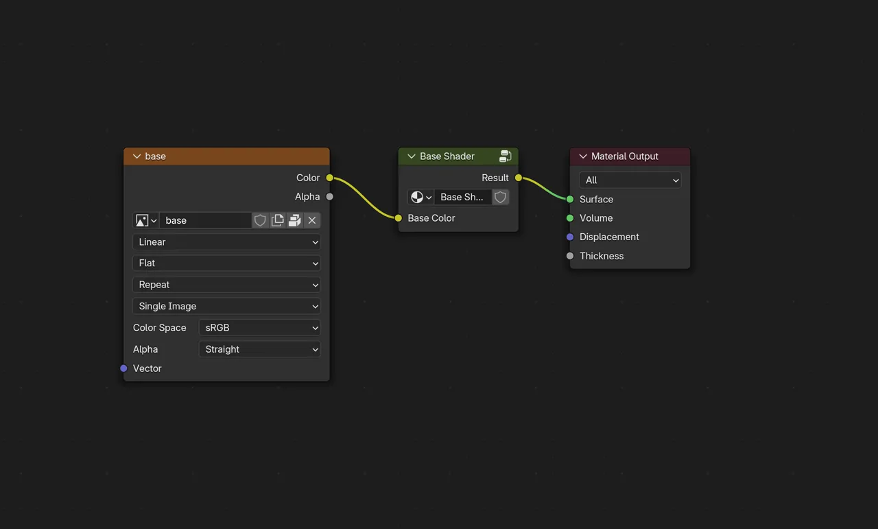
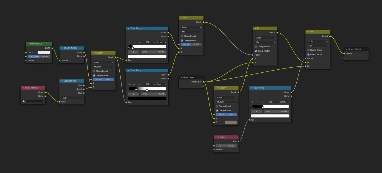
Outline Shader - Blender
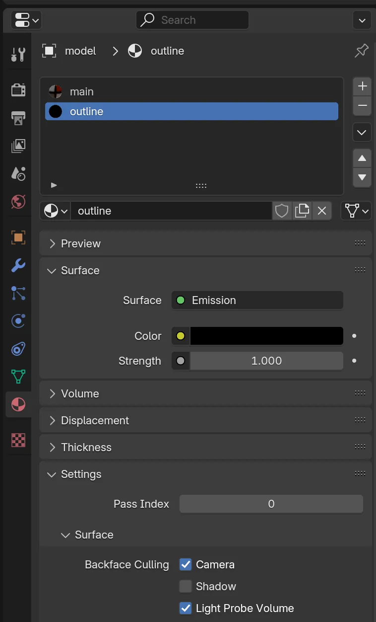
Base Shader - Godot
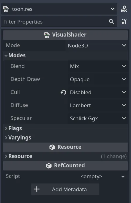
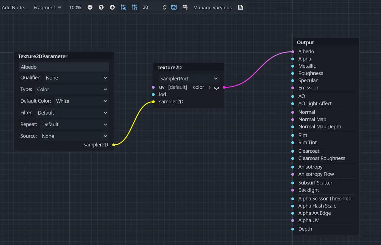
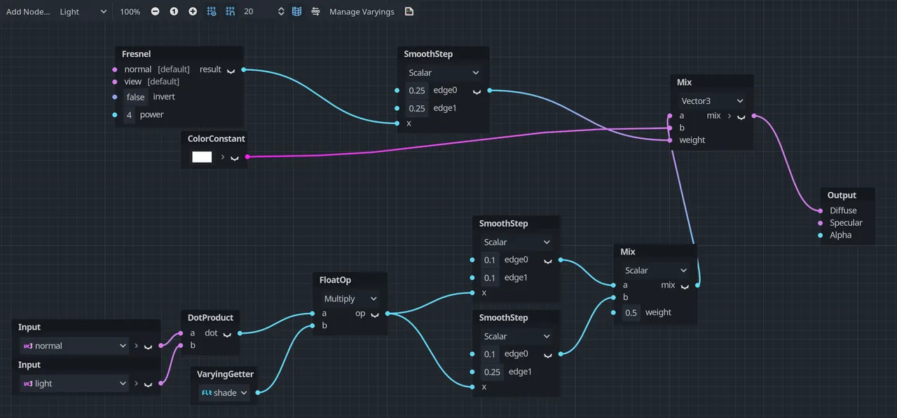
Outline Shader - Godot
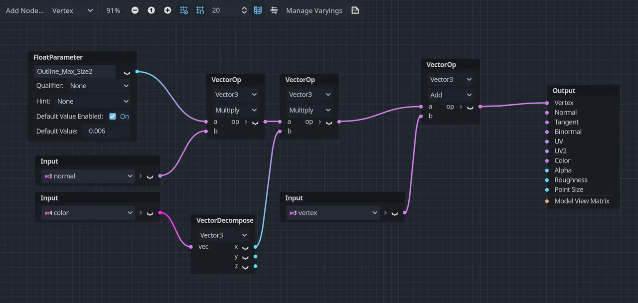
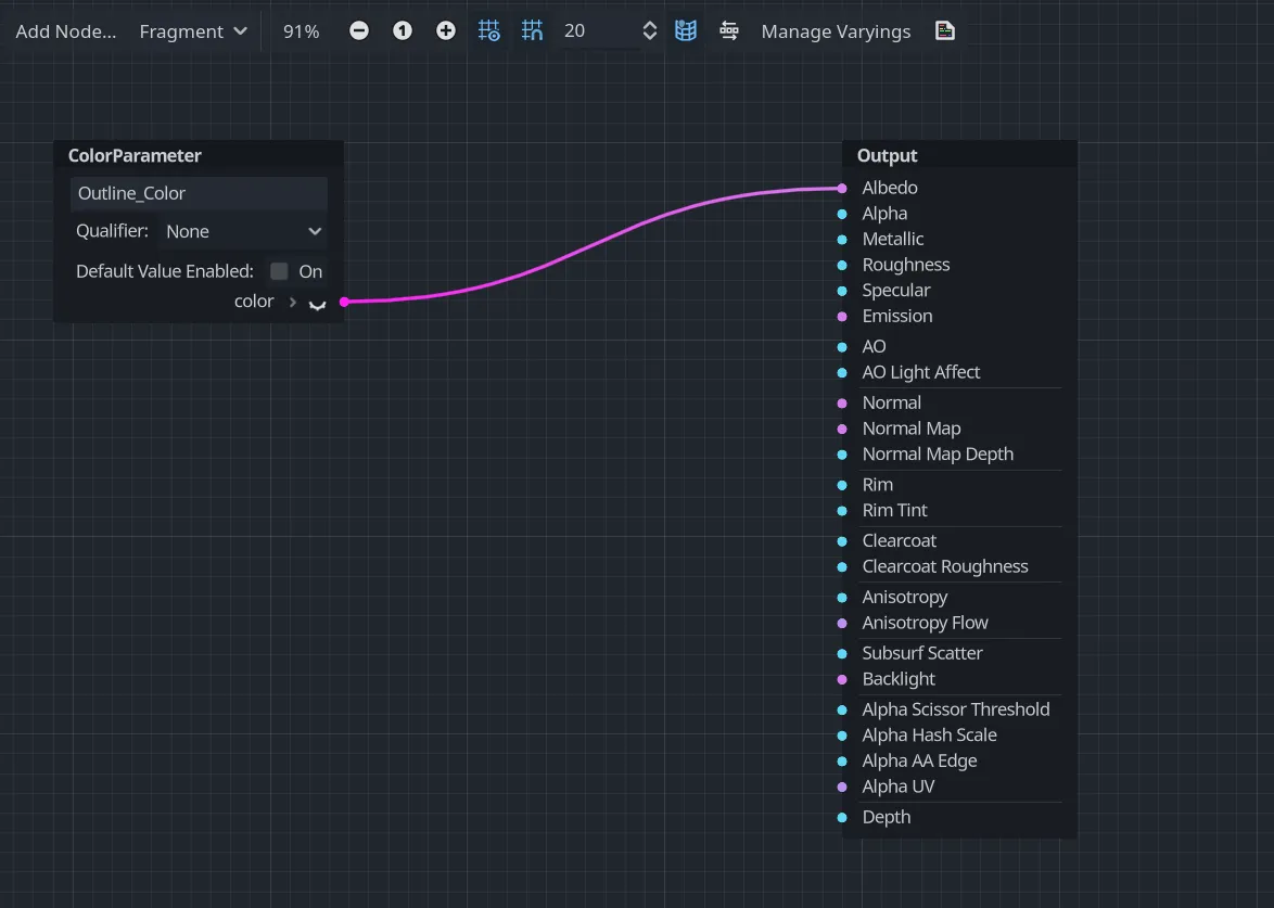
Appendix A - Terminology
3D Basics
- Vertex
- Edge
- Face
- Orthographic View
- Perspective View
- Primitive
- Axes (X, Y, Z)
- Normal
- Topology
- Polycount
- Quad
- Triangle
- N-gon
Primitives
- Cube
- Plane
- Cylinder
- Curve
- Empty
Building and Extending
- Extrusion/Extrude
- Loop Cut and Slide
- Bevel
- Inset
- Knife
- Bridge Edge Loops
- Edge Crease
- Dissolve
- Merge
- Separate
Transformation
- Grab (Move)
- Rotate
- Scale
- Shrink/Fatten
- Smooth
- Snapping
Modifiers
- Modifiers
- Mirror Modifier
- Subdivision Surface Modifier
- Array Modifier
- Curve Modifier
- Shrinkwrap Modifier
- Solidify Modifier
- Data Transfer Modifier
Properties
- Visibility
- Vertex Group
- Shape Key
Physics
- Cloth
- Pin Group
- Collision
Shading
- Shader
- Material
- Texture
- UV
- Seam
Shader Nodes
- Node
- BSDF
- Emission
- Color Ramp
- Mix RGB
Rigging
- Rig/Armature
- Rigify
- Metarig
- Bone
- Weight Paint
- Inverse Kinematics (IK)
- Forward Kinematics (FK)
Animation
- Frame
- Dope Sheet
- Action Editor
- Action
- Keyframe
- Baking
Blender Modes
- Object Mode
- Edit Mode
- Sculpt Mode
- Vertex Paint Mode
- Weight Paint Mode
- Pose Mode
3D Formats
- FBX
- gLTF/GLB
Add-ons
- F2
- Rigify
- Vertex Color Master
- Expy Kit
Other
- Scene Collection
- X-Ray
Appendix B - Frequently Used Shortcuts
General
- Access Quick Favorites: Q
- Save: CTRL+S
Navigation
- Front Orthographic View: NUMPAD1
- Right Orthographic View: NUMPAD3
- Top Orthographic View: NUMPAD7
- Opposite Orthographic View: Hold CTRL while pressing existing Orthographic View shortcut
- Perspective View: NUMPAD5
- Camera View: NUMPAD0
Object Mode
- Add Object: SHIFT+A
- Delete: X or DEL
- Switch to Edit Mode: TAB
- Join Objects: CTRL+J
- Add to Selection: SHIFT + Left Mouse Button
- Reset Position: ALT+G
- Reset Rotation: ALT+R
- Reset Scale: ALT+S
- Rename: F2
- Grab (Move): G
- Rotate: R
- Scale: S
- Select All Objects: A
- Parent: Select objects, then SHIFT and click object that will be the parent, then press CTRL+P
Edit Mode
- Vertex Select Mode: 1
- Edge Select Mode: 2
- Face Select Mode: 3
- Grab (Move): G
- Rotate: R
- Scale: S
- Shrink/Fatten or Adjust Curve Thickness: ALT+S
- Precise Adjustment: SHIFT while moving, rotating or scaling
- Select All Vertices/Edges/Faces: A
- Select Loop: ALT + Left Mouse Click
- Extrude: E
- Bevel: CTRL+B
- Inset: I or E followed by S
- Loop Cut and Slide: CTRL+R
- Fill Face: F
- Edge Crease: SHIFT+E
- Merge Vertices: M
- Separate: P
- Delete/Dissolve: X or DEL
- Open UV Menu: U
- Parent: Select objects, then SHIFT and click object that will be the parent, then press CTRL+P
Sculpt Mode
- Grab Brush: G
- Inflate Brush: I
Pose Mode
- Reset Position: ALT+G
- Reset Rotation: ALT+R
- Reset Scale: ALT+S
- Insert Keyframe: I